


- 10 -
2.10 DIMENSIONS
2.10.1 Overall Width:
36” 48”
Discharge chute down
46.25” (117.5 cm) 58.25” (148.0 cm)
Discharge chute up (Transport only)
36.1” (91.7 cm) 48.1” (122.2 cm)
2.10.2 Overall Length:
36” 48”
77.0” (196 cm) 73.0” (185 cm)
2.10.3 Curb Weight:
36” 48”
517 lbs. (234 kg) 565 lbs. (256 kg)
∗ Weights will vary slightly depending on engine option.
2.10.4 Overall Height:
36” 48”
44.1” (112 cm) 44.1” (112 cm)
2.10.5 Tread Width (to outside of tires):
36” 48”
35.2” (89.4 cm) 35.2” (89.4 cm)
2.11 TORQUE REQUIREMENTS
BOLT LOCATION TORQUE
Blade Mounting Bolt.................................................. 115-120 ft-lbs. (156-163 N-m)
Cutter Housing Spindle Nut ...................................... 140-145 ft-lbs. (190-197 N-m)
Mower Deck Support/Engine Deck Mount......................30-35 ft-lbs. (40-47 N-m)
Engine Mounting Bolts (15 HP
Kawasaki) ......................15-20 ft-lbs. (20-27 N-m)
Transmission Shifter-lever Nut.......................................30-35 ft-lbs. (40-47 N-m)
Anti-Scalp Roller Bolts....................................................40-45 ft-lbs. (54-61 N-m)
Wheel Lug Nuts .............................................................90-95 ft-lbs. (122-129 N-m)
3. ASSEMBLY INSTRUCTIONS
3.1 Uncrate unit, and remove upper handle assembly, fuel tank, and linkages from top
of crate.
3.2 Remove and open the bolt bag.
3.3 Loosen the 5/16" hardware at the two (2) discharge deflector hinge points so that
the deflector is snug, but can be moved up and down freely.
3.4 Refer to Parts Manual to help you identify and locate parts and their proper position.
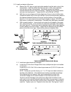
3.5 Apply retaining adhesive “Fel-Pro Retaining I or Retaining II” or “Loctite RC609 or
680” on the two threaded studs from the bolt bag and install into the two left holes
underneath fuel tank. Install the fuel tank on top of the fuel tank support with the
studs going through the slots in the support. Install two 5/16-18 x 3/4” screws with
a 5/16” SAE flat washer and 5/16” lock washer into the threaded holes in the right
side of the fuel tank. Do not over tighten. Place a 5/16” SAE flat washer, then a
spring, over each of the studs and fasten with a 5/16 nyloc nut. Tighten 5/16 nyloc
nut fully then back off a 1/2 turn. This is to allow for normal fuel tank expansion
with changes in temperature and fuel levels.
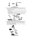
3.6 Attach the fuel tank hose to the tank fitting and secure with the clamp provided.
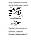
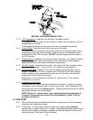
3.7 Position the lower end of the handle assembly on the outside of the upper rear
section of the fuel tank and handle support. Install four 3/8-16 x 1" bolts (with four
spring disk washers against the head of each bolt) from the outside in. Secure
using four 3/8" whizlock nuts on the inside of each handle support and tighten until
the spring disk washers are flat (See Figure 1).