


- 14 -
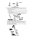
3.12 Route the long unattached wiring harness lead, up the left hand side of the handle
and connect the connector on the end of the shorter lead to the key switch.
Connect the two flag terminals that are on the longer lead (in any order) to the
operator presence control switch terminals underneath the control console.
Fasten the lead to the handle with two small wire ties from the bolt bag, one at the
upper end of the handle next to the console, and one at the very lower end of the
handle where it attaches to the fuel tank support. Fasten the lead to the small hole
in the channel under the console using another small tie from the bolt bag.
3.13 If machine is shipped without muffler installed, install muffler with hardware provided.
3.14 Service Engine: Refer to Engine Owner’s Manual.
3.15 GREASE UNIT: NOTE: UNIT IS NOT GREASED AT THE FACTORY.
Refer to 5.1.13, for locations and grease amounts.
3.16 Follow pre-start instructions as outlined in 4.2.
3.17 Perform any needed adjustments as outlined in the Adjustment Section.
4. OPERATION INSTRUCTIONS
4.1 Controls
4.1.1 Familiarize yourself with the controls and operation of the unit.
Carefully read the following information about the controls and their operation.
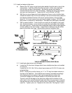
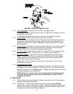
4.1.2 Operator Presence Control (OPC) Levers
: Located on the upper handle assembly
directly above the handle grips. See Figure 9. When these levers are
depressed, the OPC system senses that the operator is in the normal
operator's position. When the levers are released, the OPC system senses
that the operator has moved from the normal operating position and will kill
the engine if either the transmission shift lever is not in the neutral position or the
PTO is engaged. See Figure 9.
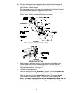
4.1.3 Drive Levers
: Located on each side of the upper handle assembly directly below the
handle grips. See Figure 9. These levers individually control the clutching action of
the wheel drive belts and the brakes. When the drive levers are all of the way out,
the brakes disengage and the wheel drive belts engage.
Gradually squeezing the left or right hand drive lever disengages the wheel drive
belts, causing the left hand or right hand wheel to slow down until they reach
neutral or stop. This makes the machine turn to the left or right respectively.
Squeezing further engages the park brakes. The sharpness of the turn varies by
how much the lever is squeezed. For straight ahead motion, smoothly release both
drive levers to engage both drive wheels simultaneously.
4.1.4 Neutral Lock/Parking Brake Latch
: Located at the end of the handles. The purpose
of these latches is to allow the operator to lock the drive levers in a "neutral" position
where neither the wheel drive belts nor the brakes engage, or in a “park brake”
position where the wheel drive belts are not engaged and the park brake is engaged.
See Figure 9.
Apply parking brakes whenever leaving the operators position.