- 12 -
4. OPERATION INSTRUCTIONS
NOTE: Determine the left and right sides of the machine from the normal operating position.
4.1 CONTROLS
4.1.1 Familiarize yourself with the controls and operation of the unit.
Carefully read the following information about the controls and their operation.
4.1.2 Blade Control Bail
:
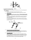
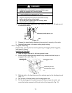
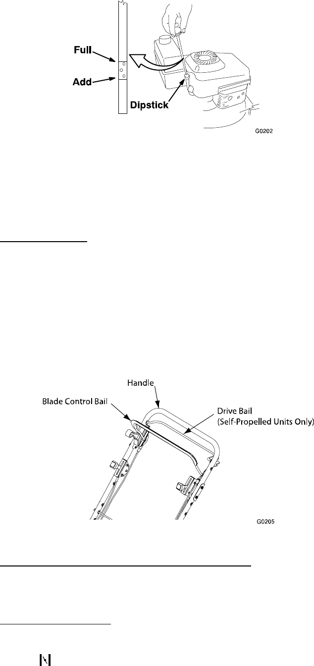
Located on the upper handle as shown in Figure 9. When the blade control bail
is depressed, the system senses that the operator is in the normal operator's
position.
For units with a Blade Brake Clutch: When the blade control bail is released, the
system senses that the operator has moved from the normal operating position
and will stop the blade.
For units without a Blade Brake Clutch: When the blade control bail is released,
the system senses that the operator has moved from the normal operating position
and will kill the engine.
4.1.3 Self-Propel Drive Bail (For Self-Propelled units only)
:
Located on the upper handle as shown in Figure 9. When the self-propel drive
bail is squeezed, the unit will move forward at the speed set on the speed control
lever. When this bail is released the unit will stop moving.
4.1.4 Throttle-Choke Control
:
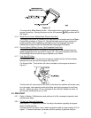
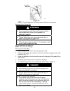
The throttle-choke control is located on the left side of the handles as shown in
Figure 10. The lever is used to control engine speed. Moving the lever to the full
forward
(Choke) position will place the lever in the choke position. The choke
aids in starting a cold engine. Moving the throttle control forward will increase
engine speed and moving it to the rear will decrease engine speed.
Figure 9
Figure 8


