


- 38 -
b) Stop engine, wait for all moving parts to stop, and remove key.
c) Check tire pressure of drive tires. If needed, adjust to 10 psi (69 kPa).
Semi-pneumatic caster tires do not need to be inflated.
d) Set anti-scalp rollers to top holes or remove them completely for this
adjustment.
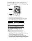
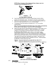
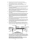
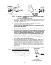
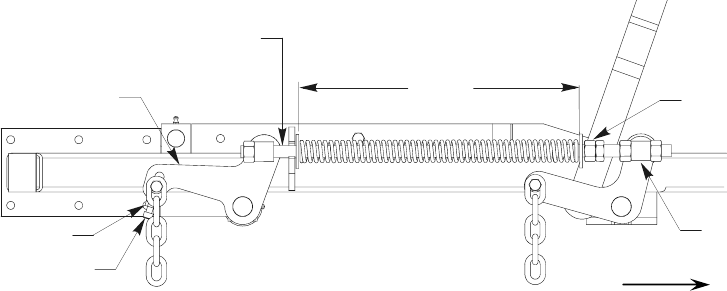
e) Raise the deck to the 5” height position (also transport position) and take all
force off of the two large deck lift springs by loosening the nuts at the front
of each spring. See Figure 13.
f) Lower the deck to the 1-1/2” height position. Force the left rear deck
support arm downward about 1/4” to get the deck to rest at the 1-1/2” height
position. Place locking pliers between the rear swivel and spring stop to
hold the deck in this position. See Figure 13.
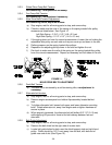
g) Place a 3/4” thick block of wood under each of the two (2) rear anti- scalp
roller brackets and place one under one of the front center anti-scalp
roller brackets.
h) Loosen the two (2) top chain bolts in slots in the rear deck lift arms. Loosen
jam nuts and back off the socket head adjusting screws on the bottom of
the arms until the chains are just loose. Turn the socket head adjusting
screws in until slack is taken out of each chain. Tighten the jam nuts.
Tighten the chain bolts in the deck lift arms making sure they don’t move
while tightening.
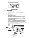
i) Loosen the four (4) nuts which secure the front swivels (two per side) until
the front chains are loose and front of deck is supported by the 3/4” block.
Do not loosen the front chain hardware.
j) On left side, adjust front swivel using the locking nut behind the swivel until
the front chain is tight and all slack is removed from linkage. Do not lift front
of deck off 3/4” block. Secure front swivel using locking nut in front of
swivel. Repeat for right side.
k) Recheck that the 3/4” blocks fit just snugly under the brackets and that the
tension on all the chains are approximately equal. Make sure all chain
attachment bolts are tight. Reposition anti-scalp rollers and tighten securely.
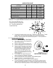
FIGURE 13
SWIVEL ADJUSTMENT
SPRING COMPRESSION ADJUSTMENT
l) Raise deck lift lever to the 5” cutting height position See Figure 8. Adjust
spring compression until proper distance is obtained between the two large
washers (See Figure 10). Adjustment is made by turning the nut at the front
of each spring (clockwise will shorten the spring, counter-clockwise will
lengthen the spring). Lock in position with jam nuts.
NOTE: When above adjustments have been made, the front of the
deck will be slightly lower than the rear of the deck.
Front of Unit
11 1/2”
Place locking pliers
here to hold spring
Apply downward
pressure here
Socket head
ad
j
ustin
g
screw
Jam nut
Remove force on
deck springs by
loosening nuts here
Swivel
G0122