


- 37 -
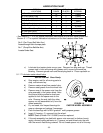
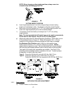
NOTE: When changing cutting height positions, always come to a
complete stop and disengage the PTO.
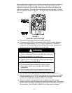
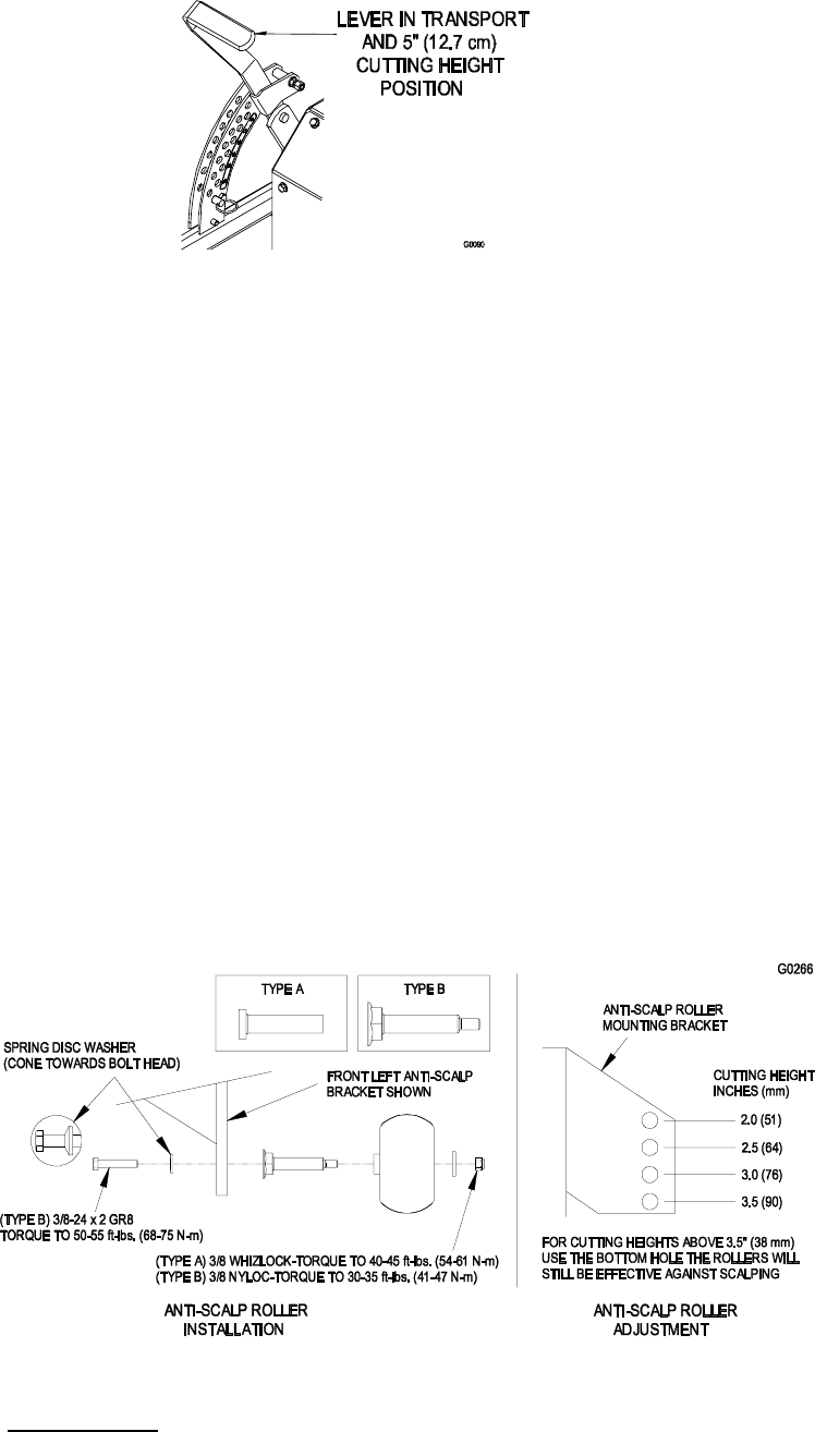
FIGURE 11
CUTTING HEIGHT POSITION
d) Insert height adjustment pin into hole corresponding to desired cutting
height and install hairpin cotter. See decals on the side of deck lift plate.
e) Move lever out of the transport (or 5” (12.7 cm) cutting height) position and
down onto height
adjustment
pin
to
mow
at
selected height.
f) To transport, move lever back up to transport (or 5” (12.7 cm) cutting
height) position.
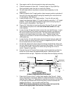
Note: The foot operated deck lift assist lever can be used to momentarily
lift the deck to clear objects. Be sure the PTO is disengaged.
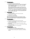
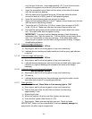
g) Adjust anti-scalp rollers for Normal Operating Conditions. Place rollers in one
of the positions shown in Figure 12. Rollers will maintain 3/4 in. (19 mm)
clearance to the ground to minimize gouging and roller wear or damage.
For Maximum Deck Flotation, place rollers one hole position lower.
Rollers should maintain 1/4 in. (6.4 mm) clearance to ground. Do Not
adjust rollers to support the deck. Be sure roller bolts and nuts are installed
with the spring disc washer between head of the bolt and mounting bracket.
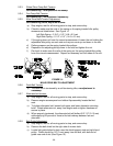
Two types of anti-scalp roller assemblies are available. See Figure 12 to
determine which assembly has been installed on the unit. Torque hardware
as specified, or loss of roller may result.
Type A – Torque the 3/8 whizlock nut to 40-45 ft-lbs. (54-61 N-m)
Type B – Torque the 3/8 nyloc nut to 30-35 ft-lbs. (41-47 N-m)
Torque the 3/8-24x2 Gr 8 hex capscrew to 50-55 ft-lbs (68-75 N-m)
FIGURE 12
ANTI-SCALP ROLLER ADJUSTMENT
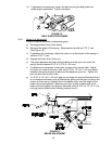
5.2.2 Deck Leveling
a) Position mower on a flat surface.