


Maintenance
Adjustments
Note: Disengage PTO, shut off engine, wait for
all moving parts to stop, engage parking brake, and
remove key before servicing, cleaning, or making any
adjustments to the unit.
CAUTION
Raising the mower deck for service or
maintenance relying solely on mechanical
or hydraulic jacks could be dangerous. The
mechanical or hydraulic jacks may not be enough
support or may malfunction allowing the unit to
fall, which could cause injury.
Do Not rely solely on mechanical or hydraulic
jacks for support. Use adequate jack stands or
equivalent support.
Deck Leveling
1. Position the mower on a at surface.
2. Stop engine, wait for all moving parts to stop, and
remove key. Engage parking brake.
3. Check the tire pressure in the drive tires. Proper
ination pressure for tires is 13 psi (90 kPa).
Adjust if necessary.
4. Position the transport lock in the latching
position.
5. Carefully rotate the blades from side to side.
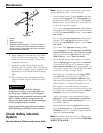
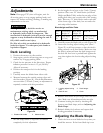
6. Measure between the outside cutting edges and
the at surface (
Figure 24). If both measurements
are not within 3/16 inch (5 mm), an adjustment is
required; continue with this procedure.
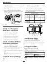
Figure 24
1. Blades side to side 2. Measure here
7. Set anti-scalp rollers to top holes or remove
completely for this adjustment.
8. Set the height-of-cut lever to the 3 inch (76 mm)
position. Place two “B” thick blocks (see Block
Height and Rake Table) under the rear edge of the
cutting deck skirt; one on each side of the cutting
deck. Place two “A” thick blocks under each side
of the front edge of the deck, but not under the
anti-scalp roller brackets.
Block Height and Rake Table
Deck
Size
Front Block
Height “A”
Rear Block
Height “B”
Rake “R”
48 &
52
2.54 inches
(6.5 cm)
2.58 inches
(6.6 cm)
1/16–5/16 inch
(1.6–7.9 mm)
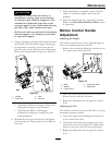
9. Carefully rotate the blades side to side (Figure 24).
10. Loosen the leveling adjust locking nuts (item 1
Figure 25) on all four corners so that the deck is
sitting securely on all four blocks. Make sure that
the slack is removed from the deck hangers and
the deck lift foot lever is pushed back against the
stop, then tighten the four leveling adjust locking
nuts.
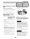
Figure 25
1. Leveling adjust locking
nuts
3. Deck hanger
2. Deck lift arm 4. Chain
11. Recheck that blocks t just snugly under the deck
skirt. Make sure all attachment bolts are tight
12. Continue leveling the deck by checking the
front-to-rear blade slope; refer to Adjusting the
Blade Slope.
13. Recheck blades for levelness and repeat deck
leveling procedure if necessary.
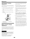
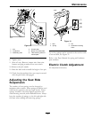
Adjusting the Blade Slope
1. Check the front-to-rear blade level any time you
install the mower. If the front blade tip is not
35