


Maintenance
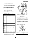
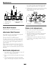
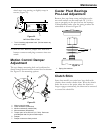
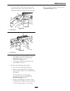
Figure 19
1. Lever down
(disengaged)
6. Remove pin to adjust
rod length for additional
brake adjustment
2. Lever up (engaged)
7. Trunnion roller
3. Nyloc nut below trunnion
roller
8. Spring retainer bracket
4. Nyloc nut below spring
9. 2 13/16 inches (7.1 cm)
5. 1/8 to 3/16 inch (3.2 to
4.8 mm)
10. Jam nut above trunnion
roller
Brake Adjustment
1. Check for brake link 2 13/16 inches (7.1 cm)
measurement as described in the Brake Link
Adjustment section.
2. Engage the brake lever (lever up). The space
between the brake spring bracket and the nyloc
nut under the spring should measure 1/8 inch to
3/16 inch (3.2–4.8 mm).
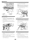
3. If adjustment is necessary, loosen jam nut above
the trunnion roller. Adjust the nyloc nut under
the trunnion roller until distance listed above
exists between the spring retainer bracket and the
adjacent nyloc nut. Tighten the jam nut above
the trunnion roller.
4. If the correct gap can no longer be achieved
because there is no clearance between the nyloc
nut below the spring and the jam nut above
the trunnion or there are no threads left on the
bottom nyloc nut, the length of the brake rod can
be adjusted. Remove a pin from a yoke at either
end of the brake rod and lengthen (or shorten) the
brake rod until the correct gap can be achieved by
following steps 2 and 3.
Electric Clutch Adjustment
No adjustment necessary.
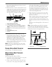
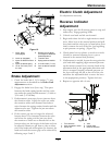
Reverse Indicator
Adjustment
1. Stop engine, wait for all moving parts to stop, and
remove key. Engage parking brake.
2. Unhook seat latch and tilt seat forward.
3. Begin with either the left or right motion control
lever. Move lever to the neutral position and pull
lever back until the clevis pin (on arm below pivot
shaft) contacts the end of the slot (just beginning
to put pressure on spring). (Figure 20).
4. Check where lever is relative to notch in console
(should be centered allowing lever to pivot
outward to the neutral lock position).
5. If adjustment is needed, loosen the nut against the
yoke and while applying slight rearward pressure
on the motion control lever, turn the head of the
adjustment bolt in the appropriate direction until
lever is centered (keeping rearward pressure on
the lever will keep the pin at the end of the slot
and allow the adjustment bolt to move the lever
to the appropriate position). Tighten lock nut.
6. Repeat on opposite side of unit.
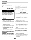
Figure 20
1. Turn bolt here 4. Yoke
2. Lever centered in notch 5. Loosen here
3. End of slot
6. Reverse indicator
41