Operation
Product Overview
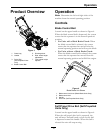
Figure 3
1. Grass bag
5. Discharge door
2. Handle 6. Rear wheel height
adjustment
3. Drive Bail
(Self-Propelled Units
Only)
7. Front wheel height
adjuster
4. Blade Control Bail
Operation
Note: Determine the left and right sides of the
machine from the normal operating position.
Controls
Blade Control Bail
Located on the upper handle as shown in Figure 4.
When the blade control bail is depressed, the system
senses that the operator is in the normal operator’s
position.
• For Units with a Blade Brake Clutch: When
the blade control bail is released, the system
senses that the operator has moved from the
normal operating position and will stop the blade.
• For Units without a Blade Brake Clutch:
When the blade control bail is released, the system
senses that the operator has moved from the
normal operating position and will kill the engine.
Figure 4
Blade Brake Unit Shown
1. Blade control lock lever (Blade Brake Units Only)
2. Blade control bail
3. Handle
4. Drive bail (Self-Propelled Units Only)
Self-Propel Drive Bail (Self-Propelled
Units Only)
Located on the upper handle as shown in Figure 4.
When the self-propel drive bail is squeezed, the
unit will move forward based on how far the bail
is depressed toward the handle. When this bail is
released the unit will stop moving.
13


