


Maintenance
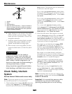
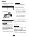
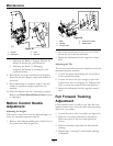
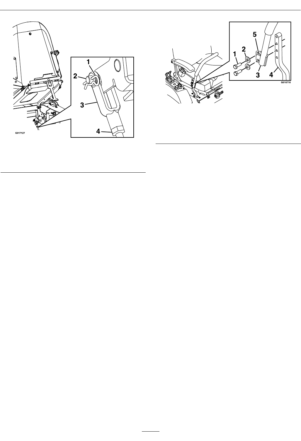
Figure 29
1. Hairpin 3. Yoke
2. Clevis pin
4. Jam nut
• Adjusting the Brake to Engage: Shorten the
linkage by turning the yoke clockwise.
• Adjusting the Brake to Disengage:
Lengthen the linkage by turning the yoke
counterclockwise.
8. Reinstall the clevis pin and hair pin and tighten
down the jam nut. Repeat step
6 and readjust if
necessary.
9. When adjustment is complete, remove the jack
stands or equivalent support and lower the
machine.
10. Place the machine into the “operating” position.
Refer to the Drive Wheel Release Valves section
in Operation.
Motion Control Handle
Adjustment
Adjusting the height:
The motion control levers can be adjusted higher or
lower for maximum operator comfort.
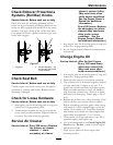
1. Remove the hardware holding the control lever to
the control arm shaft (Figure 30).
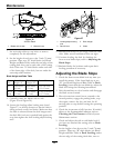
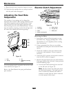
Figure 30
1. Bolts
4. Control arm shaft
2. Washer
5. Slotted hole
3. Control lever
2. Move the control lever to the next set of holes.
Secure the lever with the hardware.
3. Repeat the adjustment for the opposite control
lever.
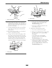
Adjusting the Tilt
The motion control levers can be tilted fore or aft for
maximum operator comfort.
1. Loosen the upper bolt holding the control lever
to the control arm shaft.
2. Loosen the lower bolt just enough to pivot the
control lever fore or aft
Figure 30. Tighten both
bolts to secure the control in the new position.
3. Repeat the adjustment for the opposite control
lever.
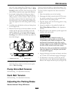
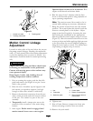
Full Forward Tracking
Adjustment
If the machine travels or pulls to one side when the
motion control levers are in the full forward position,
adjust the cover plates.
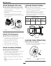
1. Loosen the screws on a cover plate (see Figure 31).
2. Slide the cover plate backward or forward to
adjust the travel of the lever and tighten the
screws.
3. Drive the machine and check the full forward
tracking.
4. Repeat steps 1 through 3 until desired tracking
is obtained.
38