


6
3002503 11.06
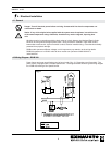
3. Mechanical Installation
3.1 General
Warning: Failure to install, maintain and/or operate the RSIB Power Venter in accordance with
the manufacturer’s instructions may result in conditions which can produce bodily injury and
property damage.
TheRSIBmustbeinstalledbyaqualiedinstallerinaccordancewiththeseinstructionsandalllocalcodes,or
in their absence, with the latest edition of The National Fuel Gas Code (NFPA54/ANSI223.1), NFPA 211, NFPA 31
or Canada CAN/CSA-B149.1-05 National Gas and Propane Installation Code when applicable. The RSIB must be
mounted so the clearance to combustibles is at least 24 inches.
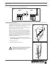
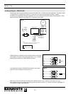
Preferably, the RSIB should be installed as close to the termination as possible. It can also be installed near the
outlet of a heating appliance in the breeching itself, or in the transition from breeching to vertical chimney (replacing
the Tee). In addition, it can be used for sidewall vented applications where it discharges through a wall. The RSIB
contains two drain holes to allow condensation to exit the fan housing.
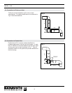
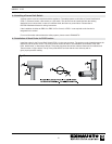
The RSIB is for indoor and outdoor installation. Unless installed adjacent to the wall it is discharging through,
the chimney material used on the discharge side must be airtight/pressure rated. Traditional gas vent (B-vent) is not
considered pressure rated or airtight. The vent pipe must be installed and supported according to the chimney
manufacturer’s instructions and/or in accordance with NFPA54, NFPA211 and Canada CAN/CSA-B149.1-05. The
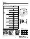
RSIBcollarstmostcommonlyavailableventsandstacks.
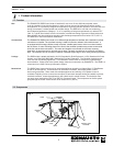
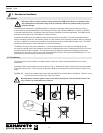
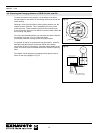
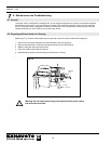
3.2 Positioning
The power venter can be installed in multiple positions. However, it should always be possible to remove the
access door.
Acceptable power venter positions are shown below in Fig. 2. Note that the power venter should never be installed
so the motor points down. This will cause condensation build up around the motor shaft and shorten the life of the
motor.
RSIB350-500: A drain hole located at the base of the motor MUST be removed prior to installation. Failure to do so
could shorten the life of the motor. See Fig. 2 below.
Warning! Never install the power venter so the motor points down. This will shorten the life. The
min. clearance to combustibles is 24 inches.
Fig. 2