


10
3002503 11.06
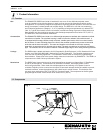
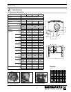
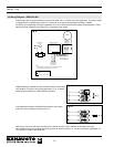
4.3 Wiring Diagram – RSIB 350-500
PowerVenterandmotorspecicationscanbefoundunder“Sec.2.1DimensionsandCapacities”.Thepowerventer
is equipped with a variable speed motor. Fig. 9 below shows a typical wiring diagram utilizing a Variable
Frequency Drive (adjusting the speed is possible). If it is not a requirement that the speed can be adjusted, a motor
starter should be installed in lieu of the VFD, if required by local codes.
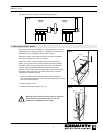
24V GAS VALVE
COM
TR
HOT
TH
PROVEN DRAFT
SWITCH
BLACK
BLACK
RED
GREEN
POWER SUPPLY
200-240/3/60
or
440-480/3/60
24 VAC
NOTES:
THE DISCONNECT MEANS AND CIRCUIT PROTECTION ARE TO
BE PROVIDED BY THE INSTALLER OF THIS DEVICE
1
All wiring must be in
flexible or rigid metal
conduit
LEGEND:
24 VAC
200-240 or 440-480 VAC
WEATHERPROOF BOX
VARIABLE FREQUENCY
DRIVE (typical)
FAN
MOTOR
L1 L2 L3 U V W
Fig. 9
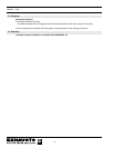
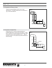
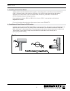
Fig. 10
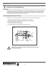
RSIB 350-500 can operate at either 3x208-230 VAC or 3x440-480
VAC (default). The motor wiring terminals shown in Fig. 10 shows
default jumper positions for 3x440-480VAC operation.
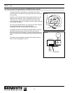
If the application requires 3x208-240VAC operation, the jumper
positions must be changed according to Fig. 11.
Fig. 11
After wiring, make sure the motor is rotating in the proper direction. This is marked on the motor end cover.
If the rotation is incorrect, swap the two wires going to the motor terminals, U1 and W1 as shown in paragraph 4.6 .
(This does NOT apply to the RSIB 300)