


6
MODEL 225 CALIBRATION
CALIBRATION
The nominal cell constant of the Model 225 sensor is
2.7/cm. The error in the cell constant is about ±10%, so
conductivity readings made using the nominal cell con-
stant will have an error of at least ±10%. Wall effects,
discussed below, will likely make the error greater. For
higher accuracy, the sensor must be calibrated.
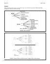
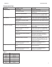
Wall effects arise from the interaction between the cur-
rent induced in the sample by the sensor and nearby
pipe or vessel walls. As Figure 11 shows, the measured
conductivity can either increase or decrease depend-
ing on the wall material. Because wall effects do not
disappear until the Model 225 sensor is at least 1 inch
(25 mm) away from the nearest wall, wall effects are
present in most installations. Correcting for them is an
important part of calibration.
Conductivity sensors are calibrated against a solution
of known conductivity (a standard) or against a previ-
ously calibrated referee sensor and analyzer. If wall
effects are present, calibrating a toroidal sensor with
a standard solution is possible only if the vessel hold-
ing the standard has exactly the same dimensions as
the process piping. Model 225 sensors are often
installed in sanitary flange tees, so an appropriate cal-
ibration vessel is another tee with blank flanges on the
ends. If removing the sensor from the process piping for
calibration is impractical, calibrate the sensor in place
against a referee sensor and analyzer while both sen-
sors are simultaneously measuring the process liquid.
If this is not practical the sensor can also be calibrated
against the results of a measurement made on a grab
sample.
For more information about calibrating toroidal conduc-
tivity sensors, refer to application sheet ADS 43-025
available on the Rosemount Analytical website.
MAINTENANCE
Generally, the only maintenance required is to keep the
opening of the sensor clear of deposits. Cleaning fre-
quency is best determined by experience.
FIGURE 11. Measured conductivity as a function
of clearance between sensor and walls
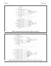
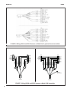
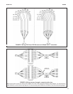
FIGURE 10. Remote Junction Box (PN 23550-00)
CAUTION
Be sure sensor has been cleaned of process liquid
before handling.