


5
MODEL 225 WIRING
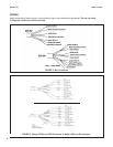
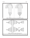
FIGURE 8. Wiring 225-54 and 225-56 sensors to Model 5081-T transmitter
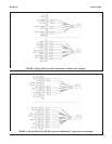
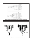
FIGURE 9. Wiring sensors through a remote junction box
Wire sensors point to point. For wiring at the analyzer end, refer to the appropriate analyzer wiring diagram. For interconnecting
cable 23294-00, use the 225-54 wiring diagram. For interconnecting cable 23294-04 and 23294-05, use the 225-56 wiring diagram.
PRESENT IN
23294-05 ONLY
AND
PN 23294-04