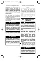
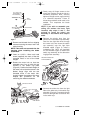
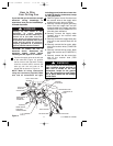
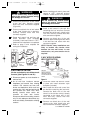
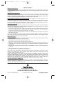
8. Carefully rest the decorative ring/light
fitter/switch cup assembly on the fan
blades, then engage the connector of
the switch cup assembly with the motor
connector (Figure 4). The two
connectors are keyed and color-coded
and must be mated correctly (color-to-
color) before they can be engaged.
Make sure the connectors are engaged
properly.
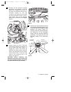
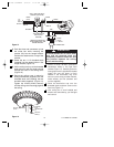
9. Partially install two 8-32 x 7mm pan
head screws (supplied) in the outer rim
of the switch cup plate (Figure 4).
Engage the L-slots in the switch cup
assembly with these screws; rotate the
switch cup and tighten the two screws.
Install another 8-32 x 7mm pan head
screw in the remaining hole in the
switch cup (Figure 5).
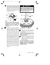
CAUTION: Before installing and
tightening the screws, be sure there are
no wires pinched between the switch
cup plate and switch cup assembly.
7
Figure 4
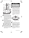
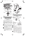
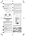
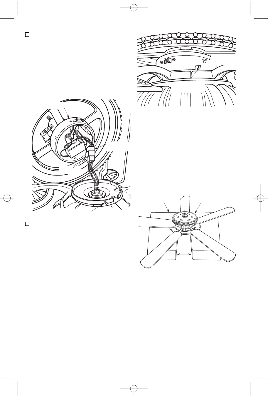
10. Position the top and bottom halves of
the styrofoam packaging side-by-side
on the floor with a six to eight inch gap
between the halves (Figure 6).
Carefully place the partially assembl-
ed ceiling fan on the styrofoam
halves, with the light fitter assembly
positioned in the gap and the fan
assembly resting on the decorative
ring.