


15
en
ASSEMBLY
Assembling the Bar and Chain
WARNING: Check the chain tension frequently when
operating the chain saw. Never touch or adjust the
chain while the engine is running. The saw chain is
very sharp, always wear protective gloves when
performing maintenance to the chain.
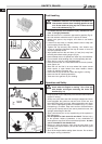
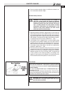
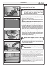
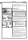
1 Ensure that the chain brake is not set by pulling the chain brake
lever / hand guard towards the front handle as shown in Fig. 20.
Refer to Safety-Chain Brake and Operation-Chain Brake
Sections for additional information.
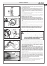
2. Remove the two (2) bar nuts
(A, Fig. 21) and the clutch cover
(B).
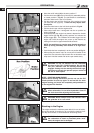
3.
Remove and discard the plastic shipping spacer (C, Fig.
22) that has been installed on the bar studs in place of the
bar for shipping purposes.
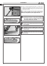
4. Adjust the chain tensioning pin (D) fully towards the rim
sprocket
(E) using the chain tensioning screw (F, Fig. 22).
5. The guide bar
(G) contains a bar stud slot that fits over the bar
studs
(H). The guide bar also contains two chain tensioning pin
holes
(I) which fit over the chain tensioning pin and two lubri-
cation holes. The bar is reversible and either tensioning pin
hole may be utilized with the chain tensioning pin.
6. Place the guide bar
(G) onto the bar studs (H) so that the chain
tensioning pin
(F) fits into the chain tensioning pin hole.
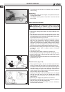
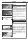
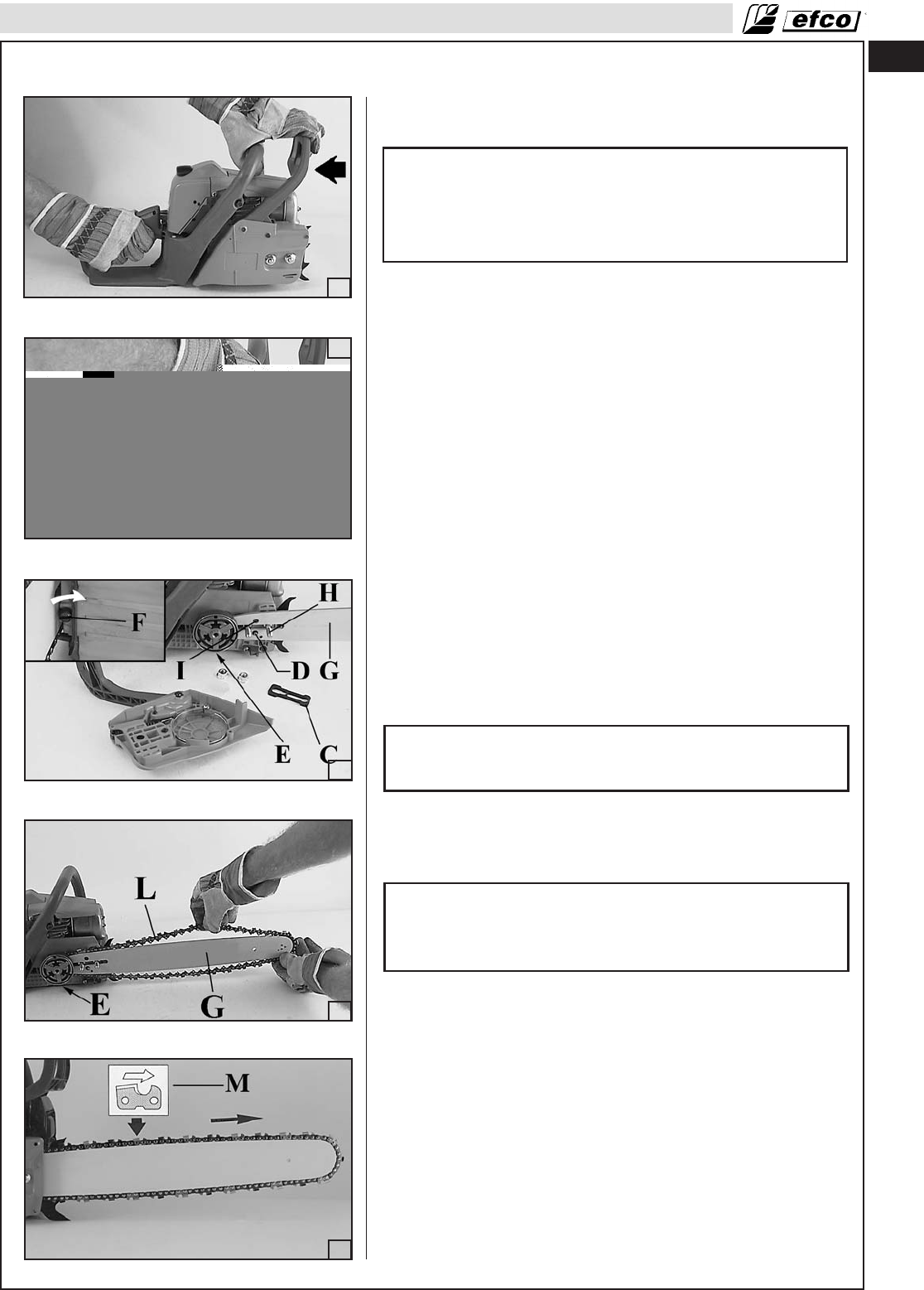
7. Position the guide bar
(G) tip through the chain (L) loop as
shown in Fig. 23. The cutters on the top of the guide bar should
face toward the bar nose, in the direction of the chain rotation.
See insert (M) in illustration below.
8. Fit the chain
(G) over the rim sprocket (E) and into bar groove.
CAUTION: Severe damage can occur to the rim
sprocket, clutch drum, guide bar and chain, if the
chain is not correctly seated into the rim sprocket.
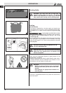
9. Replace the clutch cover (B) and install the two (2) bar nuts
(A). Tighten the bar nuts finger tight only. The bar must be free
to move for tension adjustment.
CAUTION: Failure to ensure that the chain tensioning
pin is in the chain tensioning pin hole will result in
severe damage to the chain saw during reassembly
of the clutch cover.
NOTE: If the clutch cover does not slide on freely, check that
the chain brake is not engaged. To disengage chain brake
with clutch cover removed, grasp clutch cover as shown in
Fig. 20 and pull back on chain brake lever / hand guard.
10. Remove all slack from chain by turning the chain tensioning
screw
(F) clockwise, assuring that the chain seats into the bar
groove during tensioning (Fig. 25, page 16).
11. Lift the tip of the guide bar up to check for sag, see Fig. 26,
pag. 16. Release the tip of the guide bar, and turn the chain
tensioning screw
(F) 1/2 turn clockwise. Repeat this process
until sag does not exist.
12. Hold the tip of the guide bar up and tighten the bar nuts
securely as shown in Fig. 27, page 16.
ƽ
ƽ
ƽ
20
22
23
24
21