


5
ASSEMBLY
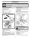
TILLER
HANDLES
CABLE
HANDLE
PANEL
BOLTS
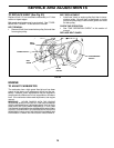
FIG. 2
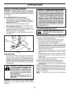
HAN DLE
PANEL
HEX BOLT
5/16-18X3/4"
TILLER
HANDLE
HEX BOLT
5/16-18X1"
FLAT
WASHER
LOCK
WASH ER
NUT
DEPTH
STAKE
SUPPORT
BOLT
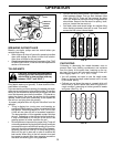
HEX BOLTS,
LOCK WASH ERS,
AND HEX NUTS
DEPTH STAKE
SUPPORT
NUT “A”
ENGINE BRACK ET
HALVES
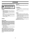
FIG. 3
STAKE
SPRING
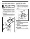
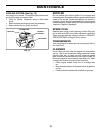
INSTALL DEPTH STAKE ASSEMBLY
(See Fig. 3)
• Loosen nut “A”.
• Insert stake support between engine bracket halves
with stake spring down.
• Bolt stake support to engine brackets with bolts, lock
washers and nuts. Tighten se curely. Tighten nut “A”.
• Depth stake must move freely. If it does not, loosen
support bolt.
HANDLE HEIGHT
• Handle height may be adjusted to better suit operator.
(See “HANDLE HEIGHT” in the Service and Ad just -
ments section of this manual).
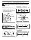
TILLING WIDTH
• Tilling width may be adjusted to better handle your
tilling con di tions (See “TINE ARRANGEMENT” in the
Ser vice and Adjustments section of this manual).
TINE OPERATION
• Check tine operation before fi rst use. (See “TINE OP-
ERATION CHECK” in the Service and Adjustments
section of this manual).
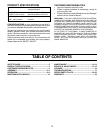
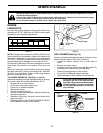
UNPACK CARTON & INSTALL HANDLE (See
Fig. 2)
CAUTION: Be careful of exposed
sta ples when handling or disposing
of cartoning material.
IMPORTANT: WHEN UNPACKING AND AS SEM BLING
TILLER, BE CAREFUL NOT TO STRETCH OR KINK
CABLE(S).
• Cut cable ties securing handles.
• The handle may be assembled in high or low position.
Slowly lift handle as sem bly up, route cable(s) as shown
and align han dle holes with desired handle panel hole
and slot.
• Loosely assemble hardware as shown. Be sure the
shorter (3/4" long) hex bolt is assembled in lower
hole of handle. Repeat for opposite side. Tight en all
hard ware se cure ly.
NOTE: Cables must not touch the muffl er.
• Cut cable ties securing tiller to skid and remove tiller
from skid.
• Remove screws securing depth stake to skid and dis-
card the screws.