


13
TILLER
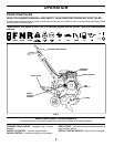
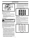
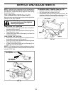
TO ADJUST HANDLE HEIGHT (See Fig. 15)
Factory assembly has provided lowest handle height. Se lect
handle height best suited for your tilling conditions. Handle
height will be different when tiller digs into soil.
• If a higher handle height is desired, loosen the four
nuts securing handle panel to engine brackets.
• Slide handle panel to desired location.
• Tighten the four nuts securely.
HANDLE
PANEL
ENGINE
BRACKETS
NUTS (ALSO 2
ON LEFT SIDE
OF TILLER)
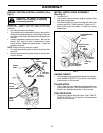
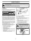
CAUTION: Disconnect spark plug wire from spark plug and place wire where it cannot come into
contact with plug.
SERVICE AND ADJUSTMENTS
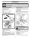
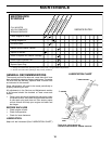
TINE ARRANGEMENT
Your outer tines can be assembled in several different ways
to suit your tilling or cultivating needs.
CAUTION: Tines are sharp. Wear
gloves or other protection when han-
dling tines.
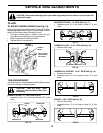
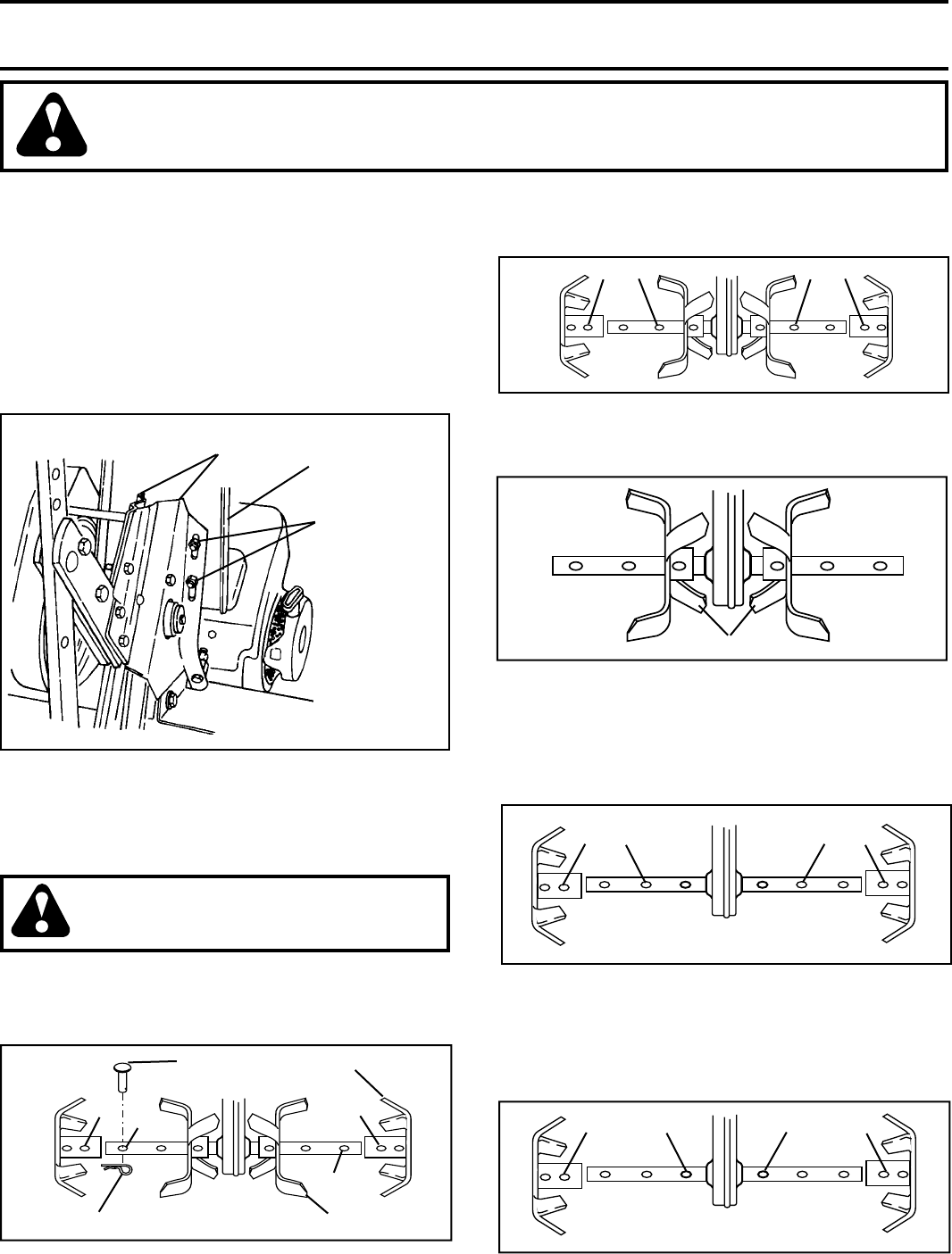
NORMAL TILLING - 17" PATH (See Fig. 16)
• Assemble holes “A” in tine hubs to holes “B” in tine
shaft.
FIG. 16
FIG. 17
B
A
CLEVIS
PIN
INNER TINE
OUTER TINE
B
A
HAIRPIN CLIP
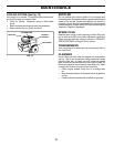
MID-WIDTH TILLING - 15" PATH (See Fig. 17)
• Assemble holes “A” in tine hubs to holes “C” in tine
shaft.
A
C C A
FIG. 15
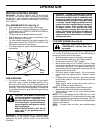
INNER TINES ONLY
FIG. 18
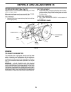
NARROW TILLING - 10-1/4" PATH (See Fig. 18)
• Remove outer tines.
NARROW CULTIVATING - 12-1/2" PATH (See Fig. 19)
• Remove inner tines.
• Assemble holes “A” in tine hubs to holes “C” in tine
shaft.
A
C
C
A
FIG. 19
A
A
D
D
FIG. 20
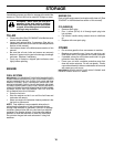
EDGING - 9-5/8" PATH (See Fig. 20)
• Remove inner tines.
• Assemble holes “A” in tine hubs to holes “D” in tine
shaft.