


24
01513
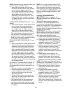
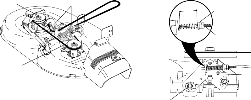
Do Not touch this nut. If further brake
ad just ment is necessary contact an authorized
service center/department.
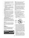
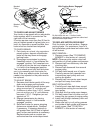
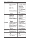
Jam Nut
Operating
Arm
Nut “A”
With Parking Brake “Engaged”
1-9/16”
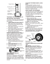
TO CHECK AND ADJUST BRAKE
Your tractor is equipped with an ad just able
brake system which is mounted on the
right side of the transaxle.
If tractor requires more than fi ve (5) feet to
stop at highest speed in high est gear on a
level, dry concrete or paved surface, then
brake must be checked and ad just ed.
TO CHECK BRAKE
1. Park tractor on a level, dry concrete or
paved surface, depress clutch/brake
pedal all the way down and engage
parking brake.
2. Disengage transmission by placing
freewheel control in “transmission dis-
engaged” position. Pull freewheel con-
trol out and into the slot and release so
it is held in the disengaged position.
The rear wheels must lock and skid when
you try to manually push the tractor for-
ward. If the rear wheels rotate, the brake
needs to be adjusted or the pads need to
be replaced.
TO ADJUST BRAKE
1. Depress clutch/brake pedal all the way
down and engage parking brake.
2. Measure distance between brake oper-
ating arm and nut “A” on brake rod.
3. If distance is other than 1-9/16", loosen
jam nut and turn nut “A” until distance
becomes 1-9/16". Retighten jam nut
against nut “A”.
4. Engage transmission by placing
free wheel control in “trans mis sion
en gaged” position.
5. Road test tractor for proper stopping
distance as stated above. Readjust
if nec es sary. If stopping distance is
still greater than fi ve (5) feet in high est
gear, further main te nance is nec es sary.
Replace brake pads or contact our
authorized service center/department.
0231
4
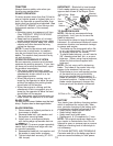
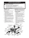
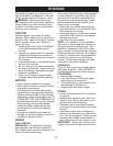
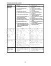
Mandrel
Pulley
Mandrel
Pulley
Idler Pulleys
TO REPLACE MOTION DRIVE BELT
Park the tractor on level surface. En gage
parking brake. For as sis tance, there is a
belt installation guide decal on bottom side
of left footrest.
BELT REMOVAL -
1. Remove mower (See “TO RE MOVE
MOWER” in this section of manual).
NOTE: Observe entire motion drive belt
and position of all belt guides and keepers.
2. Remove belt from stationary idler and
clutching idler.
3. Remove belt downward from around
en gine pulley.
4. Pull belt slack toward rear of trac tor.
Carefully remove belt upwards from
transmission input pulley and over
cooling fan blades.
5. Remove belt from center span keeper
and pull belt away from tractor.
BELT INSTALLATION -
1. Carefully work new belt down around
transmission cooling fan and onto the
input pulley.
2. Slide belt into the center span keeper.
3. Pull belt toward front of tractor and roll
around the top groove of engine pulley.
4. Install belt through stationary idler and
clutch ing idler.
5. Make sure belt is in all pulley grooves
and in side all belt guides and keep ers.
6. Install mower (See “TO IN STALL
MOWER” in this sec tion of manual).