


GRASS TRIMMER/BRUSH CUTTER
OPERATOR'S MANUAL
13
ASSEMBLY
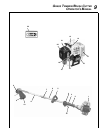
POWER
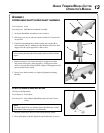
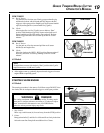
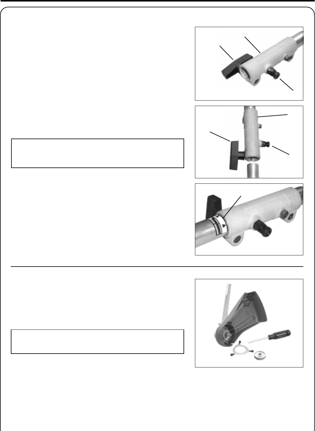
HEAD SHAFT/LOWER SHAFT ASSEMBLY
Tools Required: None
Parts Required: Split Boom Attachment Assembly
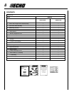
1. Set Power Head/Shaft Assembly on a level surface.
2. Pull locator pin (A) out, and turn counter-clockwise 1/4 turn to lock-
out position.
3. Carefully fit attachment drive shaft assembly into coupler (B) to
decal assembly line (C), making sure that the inner lower drive shaft
engages into the square upper drive shaft socket.
NOTE
Lower bearing housing and head assembly must be in line with the
engine.
4. Rotate locator pin (A) 1/4 turn clockwise to engage lower shaft
hole. Insure locator pin is fully engaged by twisting lower drive
shaft. Locator pin should snap flush in coupler. Full engagement will
prevent further shaft rotation.
5. Secure lower shaft assembly to coupler by tightening clamping
knob (D).
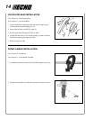
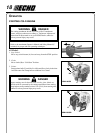
PLASTIC SHIELD INSTALLATION
(For Nylon Line Operation)
Tools Required: Screwdriver.
Parts Required: Plastic Shield, Shield Plate, three (3) 5 mm x 15 mm
screws.
NOTE
The plastic shield is for use with the Nylon Line Head only. Install
Metal Shield when using plastic or metal blades.
1. Snap the shield on the bottom of the bearing housing flange.
2. Place shield plate on shield, align holes and install three (3) screws.
D
A
A
B
D
C
B