


GRASS TRIMMER/BRUSH CUTTER
OPERATOR'S MANUAL
19
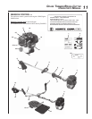
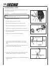
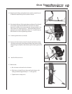
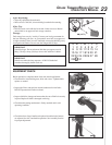
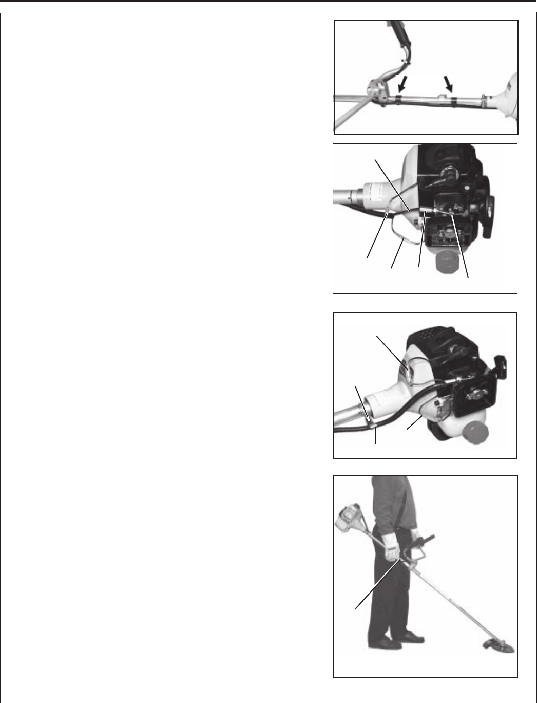
12. Route throttle linkage and ignition lead assembly around front of
U-Handle bracket and clip to drive shaft as shown.
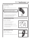
13. Place throttle linkage (E) through adjustment fixture (F) and install
wire end into large carburetor throttle swivel hole (D). Check
throttle for freedom of movement and that wide open throttle / low
idle extremes are adjusted properly. The throttle linkage must be
adjusted by moving the adjustment fixture (F). Consult with your
Echo Dealer for correct adjustment procedure.
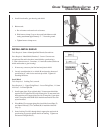
14. Connect ignition leads (A) and (B).
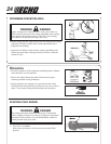
15. Remove left side clutch case bolt (P). Install metal bracket clamp
(Q) with curved end up. Install throttle linkage into bracket clamp
and pinch tight with pliers. Bend bracket up and flush against drive
shaft.
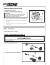
16. Install air filter and cover.
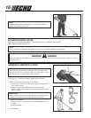
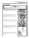
17. Balance unit.
a. Put on harness and attach unit to harness.
b. Slide harness clamp (R) up or down until unit balances with
cutting attachment approximately 2 - 3" from ground.
c. Tighten harness clamp screw.
A
B
P
Q
R
A
B
D
E
F