GRASS TRIMMER/BRUSH CUTTER
OPERATOR'S MANUAL
17
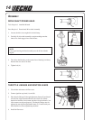
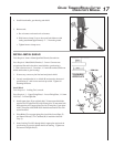
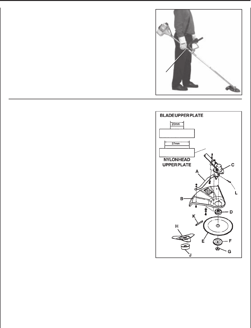
INSTALL METAL SHIELD
Tools Required: 8mm x 10mm Open End Wrench, Screwdriver.
Parts Required: Metal Shield, Bracket, 3 - 5 mm x 15 mm screws
w/captivated flat and lockwasher (metal shield to gear housing),
2 - 5 mm x 8 mm screws, 4 - 5 mm nuts, 4 - 5 mm lockwashers (bracket to
shield and bracket to gear housing).
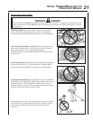
1. If necessary, remove nylon line head and plastic shield.
2. Loosely attach bracket (A) to shield (B) and attach to bottom of
gear housing (C) with screws and nuts provided. Tighten all
attaching hardware.
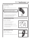
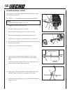
Install Blade
Tools Required: Locking Tool, scrench.
Parts Required: 1 - Upper Fixing Plate, 1 - Lower Fixing Plate, 1 - 10 mm
L.H. Nut, 1 - 2x22 mm Split Pin.
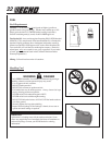
3. Install upper plate (D) on splined shaft. 20 mm center hole blade
requires use of Upper Plate (D) with 20 mm pilot. 25 mm center hole
blade requires use of upper plate (D) with 25 mm pilot. Upper plate
with 37 mm pilot of the SRM-2601 should be retained for use with
nylon line head.
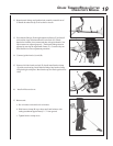
4. Place Blade (E) over upper plate pilot, install the Lower Plate (F)
and 10mm LH nut (G). Tri-Cut Blade (H) is installed with Glide
Cup (J).
5. Insert Locking Tool (K) through hole in upper plate and notch in
gear housing to prevent splined shaft from turning. Tighten nut
and secure with Split Pin (L).
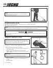
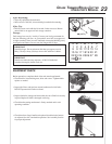
4. Install front handle, gear housing and shield.
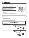
5. Balance unit.
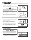
a. Put on harness and attach unit to harness.
b. Slide harness clamp (J) up or down until unit balances with
cutting attachment approximately 2" - 3" from the ground.
c. Tighten harness clamp screw.
J
SRM-2601


