14
Install Blade
Tools Required: Locking Tool, Scrench.
Parts Required: Upper Plate w/ 20 mm pilot, Lower Plate, 10 mm Nut
w/L.H. threads, 2 x 25 mm Cotter Pin, Blade.
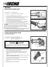
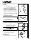
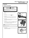
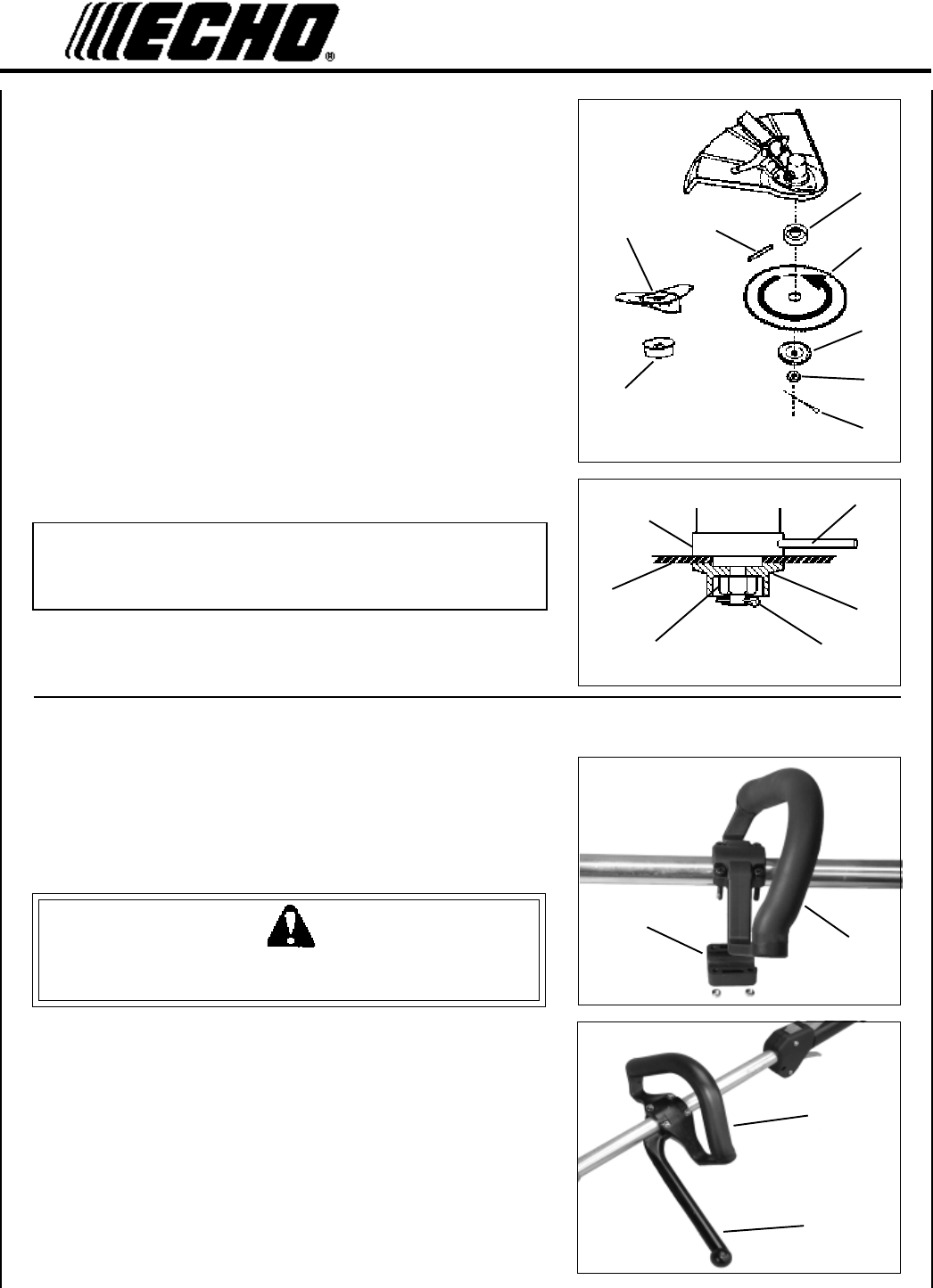
1. Install upper plate (D) on splined PTO shaft, pilot side down.
Blade installation requires Upper Plate (D) with 20 mm pilot.
2. Install Blade (L) on upper plate pilot. Blades must be installed so
that rotation arrow on blade matches rotation of unit: teeth toward
direction of rotation (See debris shield decal). Secure blade with
Lower Plate (C), and 10 mm L.H. nut (B). Turn nut counter-clockwise
on PTO shaft to tighten.
3. Align hole in upper plate with notch in gear housing, and insert
Locking Tool (H) to prevent splined shaft from turning. Arrow on
gear housing points to notch. Tighten 10 mm nut securely.
4. Insert Split Pin (A) in hole in PTO shaft, and bend pin legs around
shaft counterclockwise to retain 10 mm nut.
IMPORTANT
Never reuse a cotter pin - install a new cotter pin each time a blade is
installed or replaced.
5. Tri-Cut Blade (M) is installed with Glide Cup (N).
6. Remove locking tool.
D
20
H
L
B
A
C
D
L
C
B
A
HM
N
FRONT HANDLE/BARRIER BAR INSTALLATION AND ADJUSTMENT
A
A
B
C
Tools Required: Screwdriver.
Parts Required: Loop Handle Assembly: Loop Handle, Loop Handle
Bracket, 5mm x 35mm Screws (4), 5mm Nuts (4)
Optional: Barrier Bar, P/N 99944200455
WARNING DANGER
The Barrier Bar must be installed when using grass or weed blades,
otherwise serious personal injury may result.
Handle Only
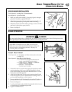
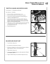
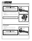
1. Install loop handle (A) and handle bracket (B) on drive shaft, and
position for comfortable operation. Tighten screws.
Handle and Barrier Bar
1. Install loop handle (A) and barrier bar (C) on drive shaft, and
position for comfortable operation. Tighten screws.


