


12
ASSEMBLY
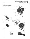
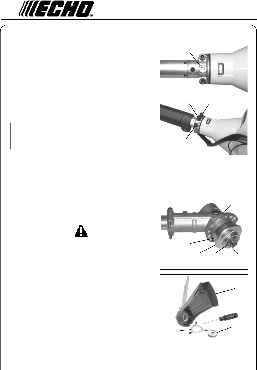
DRIVE
SHAFT/POWER HEAD
Tools Required: 4 mm Hex Wrench
Parts Required: Power Head, Drive Shaft Assembly
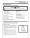
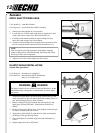
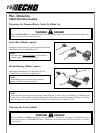
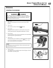
1. Stand power head upright on a level surface.
2. Loosen the two (2) drive shaft clamp bolts at engine drive shaft
clamp, and remove center drive shaft location bolt (A).
3. Carefully fit driveshaft assembly to engine making sure that
inner drive shaft engages into clutch mount.
4. Turn drive shaft housing until locating hole lines up with location
hole in clamp and install center drive shaft location bolt (A).
NOTE
Gear housing must be aligned properly with engine. Aligning
center locating hole in driveshaft housing with center drive shaft
bolt (A) provides correct alignment.
5. Tighten two (2) drive shaft clamp bolts (B) securely.
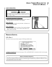
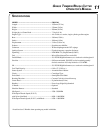
PLASTIC SHIELD INSTALLATION
(Nylon line operation)
Tools Required: Screwdriver, Locking Tool
Parts Required: Plastic Debris Shield, Shield Plate,
three (3) 5 x 16 mm screws.
WARNING DANGER
The plastic shield is for use with the Nylon Line Head only. Install
Metal Shield when using plastic or metal blades, or serious injury
may result.
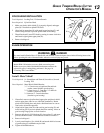
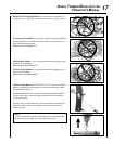
1. Align hole in upper plate (D) with notch in gear housing (G), and
insert locking tool to prevent splined shaft from turning. Arrow on
gear housing flange points to notch location.
2. Remove cotter pin (A), L.H. blade nut (B), lower plate (C), and
upper plate (D) from PTO shaft. Turn blade nut clockwise to
remove.
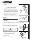
3. Remove locking tool. Retain lower plate, blade nut, and cotter pin
for future use with blade conversions.
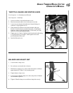
4. Align plastic debris shield (F) with the drive shaft, and install on
the bottom of the gear housing flange.
5. Place shield plate (E) on shield, align holes and install three (3)
screws.
6. Replace upper plate (D) on PTO shaft.
E
D
F
A
A
B
B
C
B
A
D
G