


27
RM-4000/4000SI/5000
E
N
G
L
I
S
H
D
E
U
T
S
C
H
I
T
A
L
I
A
N
O
Als zweites wird die biegsame Welle mit dem Motorblock
verbunden.
•Während dem Drücken des Sicherheitssfiftes führen Sie
die biegsame Welle (R) In die Gehäuseaufnahme ein,
•Ziehen Sie die immer bewegliche Welle ca. 4 mm heraus,
wodurch das Einführen erleichtert wird.
•Nach dem Loslassen des Sicherungsstiftes vergewissern
Sie sich bitte, daß die Welle nicht mehr herausgezogen
werden kann.
lst dies der Fall, so ist sie richtig montiert.
Die Verbindung des Gaszuges und des Stop-Kabel ist
so ausgelegt, daß sie einfach und ohne Vorkenntnisse
montiert werden könnon
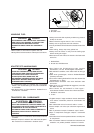
1
23
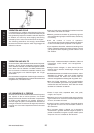
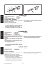
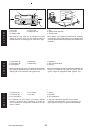
1. Lock pin
2. Push
3. Power transmission shaft (R)
Second stage is coupling of the power transmission shaft
(R) and the engine.
•As pushing in the lock pin fully, insert the other end of
power transmission (R) to the driving shaft of the engine.
- For easier coupling, pull out the power transmission (R)
about 4 mm more in advance.
•After set the lock pin free, confirm that the flexible shaft
assembly can not be drawn out and is coupled properly
with the engine.
La seconda fase consiste nell’accoppiamento dell’albero
di trasmissione (R) al motore.
1.Spina di blocco
2.Pulsante
3.Asta trasmissione (R)
1. Sicherungsstift
2. Drücken
3. Biegsame Welle (R)
•Spingendo bene nel perno di blocco, inserire l’altra
estremitá della trasmissione (R) nell’albero motore.
- Per un accoppiamento piu facile tirare fuori la
trasmissione (R) di circa 4 mm in piú.
•Dopo aver liberato il perno di blocco assicurarsi che il
flessibile non possa saitar fuori e che sia collegato
adeguatamente al motore.
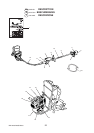
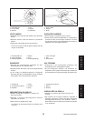
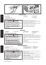
1. Joint
2. Inner cable
3. Holder
4. Lead (A)
5. Lead (B)
6. Throttle cable
7. Cover (A)
8. Cover (B)
1. Verbindungsstück
2. Gaszug
3. Halter
4. Stopkabel (A)
5. Stopkabel (B)
6. Gaszughülle
7. Schutzhülle (A)
8. Schutzhülle (B)
1. Raccordo
2. Cavo interno
3. Supporto
4. Filo di massa (A)
5. Filo di massa (B)
6. Filo acceleratore
7. Coperchio (A)
8. Coperchio (B)
1
2
3
4
5
8
7
6
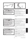
THROTTLE CABLE RETAINER ASS’Y
This ass’y is designed to provide a simple connection and
adjustment for the throttle cable.
•Hook inner cable terminal into joint, set the cable in
holder and shut cover (A).
•Connect lead (A) and lead (B).
GASZUGVERBINDUNG
Der Gaszugverbinder ist so konstruiert, dass die Gaszüge
damit leicht verbunden und eingestellt werden können.
•Den Gaszug in das Verbindungsstück einhängen und
die Schutzhülle (A) schließen.
•Verbinden Sie jeweils Kabel (A) und (B) miteinander.
FERMO FILO ACCELERATORE
Questo assemblato serve a provvedere in modo semplice
alla connessione e alla regolazione del cavo acceleratore.
•Agganciate il cavo terminale nella ginutura, fissate il
cavo al supporto e chiudete il coperchio (A).
•Collegare il filo di massa (A) e il (B).