


23
RM-4000/4000SI/5000
E
N
G
L
I
S
H
D
E
U
T
S
C
H
I
T
A
L
I
A
N
O
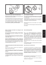
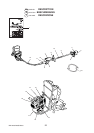
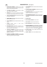
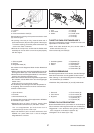
DESCRIPTION
GB
(See page 22)
1 OPERATOR’S MANUAL Included with unit. Read
before operation and keep for future reference to learn
proper, safe operating techniques.
2 CUTTING ATTACHMENT 3 cutter blade for cutting
grass, garden debris and weeds.
3 SHIELD Device to protect the operator from acciden-
tal contact with the cutting head and thrown objects.
4 ANGLE TRANSMISSION Having two gears to change
the angle of rotating axis.
5 SHAFT TUBE Part of the unit that provides a casing for
power transmission shaft.
6 FRONT HANDLE Handle located towards the cutting
device.
7 STRAP Rubber strap to hang power
transmission shaft assy.
8 IGNITION SWITCH “Slide Switch” mounted on top of
the Throttle Trigger Housing, move switch forward to
RUN, backward to STOP position.
9 THROTTLE TRIGGER Spring loaded to return to idle
whenreleased. When accelerating, press trigger
gradually for best operating technique, DO NOT hold
trigger when starting.
10 THROTTLE TRIGGER LOCKOUT Locks throttle
trigger in the idling position until you have a proper grip
with your right hand around the handle.
11 REAR HANDLE Handle located towards the knapsack
power unit.
12 FLEXIBLE SHAFT ASSEMBLY Flexible tube for the
power transmission shaft.
13 SILENCER COVER Cover for the silencer to prevent
operator contact with the hot exhaust.
14 DECOMPRESSION DEVICE - Device for lowering the
compression in the cylinder, to aid starting. (RM-4000,
RM-5000)
15 SPARK PLUG
16 AIR CLEANER COVER Covers air filter.
17 FUEL TANK Contains fuel and fuel filter.
18 FUEL TANK CAP For closing the fuel tank.
19 STARTER HANDLE Pull handle slowly until starter
engages, then quickly and firmly. When engine starts,
return handle slowly. DO NOT let handle snap back or
damage to unit will occur. (RM-4000SI ;
START)
20 BLADE COVER Cover for blade used when unit is
being transported.
21 SAFETY DECAL Part number 890617-43130