


8
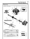
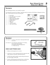
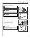
1. POWER HEAD - Factory Assembled. Includes the Engine, Clutch, Fuel System, Ignition System and Recoil
Starter.
2. THROTTLE HANDLE - FOR RIGHT HAND - Contains Stop Switch, Throttle Lockout, and Throttle Trigger.
3. THROTTLE TRIGGER LOCKOUT - This lever must be held during starting. Operation of the throttle trigger is
prevented unless throttle trigger lockout lever is engaged.
4. STOP SWITCH - Controls engine ignition. Move switch forward to start and run engine, back to “STOP” position
to stop engine.
5. HAND GUARD / BLADE LOCK - Locks blade in place for travel / storage. Always assure blade cover is in-
stalled when locking blade.
6. BLADE INDEXING RING- Pull ring out and turn 1/4 turn to lockout position when adjusting blade angle.
7. BLADES - Double reciprocating blades mounted to a blade support bar. Double-sided blades are capable of cutting
on either side of the blade.
8. GEAR HOUSING ASSEMBLY - Gear housing contains drive gears for transmitting power to cutting blades. Piv-
oting design permits blades to articulate 180 degrees in 15-degree increments.
9. BLADE ADJUSTMENT HANDLE - Provides secure hand grip for adjusting cutting blade angle.
10. SUPPORT HANDLE - FOR LEFT HAND - Cushioned hand grip for gripping drive shaft assembly.
11. DRIVE SHAFT ASSEMBLY - Includes the ex drive shaft, rear handle assembly, harness ring, cushioned front
shaft grip, and safety decals.
12. THROTTLE TRIGGER - Controls engine speed. Spring loaded to return to idle when released. During accelera-
tion, depress gradually for best operating technique.
13. BLADE COVER - Used to cover blade during transport and storage. Remove blade cover before using unit.
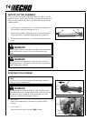
14. SPARK ARRESTOR MUFFLER OR SPARK ARRESTOR MUFFLER WITH CATALYST -The mufer or
catalytic mufer controls exhaust noise and emission. The spark arrestor screen prevents hot, glowing particles of
carbon from leaving the mufer. Keep exhaust area clear of ammable debris.
15. FUEL TANK - Contains fuel and fuel lter.
16. RECOIL STARTER HANDLE - Pull handle slowly until starter engages, then quickly and rmly. DO NOT pull
rope all the way out or allow the handle to snap back, damage to the starter will occur.
17. FUEL TANK CAP - Covers and seals fuel tank opening.
18. PURGE BULB - Pumping purge bulb before starting engine draws fresh fuel from the fuel tank, purging air from
the carburetor. Pump purge bulb until fuel is visible and ows freely in the clear fuel tank return line. Pump purge
bulb an additional 4 or 5 times.
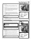
19. AIR CLEANER - Contains replaceable lter element.
20. CHOKE CONTROL - Located on the top of the air cleaner housing. Move the lever to “COLD START” ( ) to
close the choke for Cold Starting. Move lever to “RUN” ( ) position after engine res.
21. SPARK PLUG - Provides spark to ignite fuel mixture.
22. TOP GUARD - Protects arm from the hot engine.
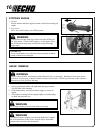
23. SHOULDER HARNESS - An adjustable strap that suspends the unit from the operator.