


10
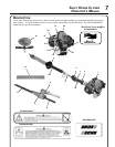
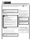
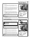
5. Tighten two (2) drive shaft clamp bolts (B) securely.
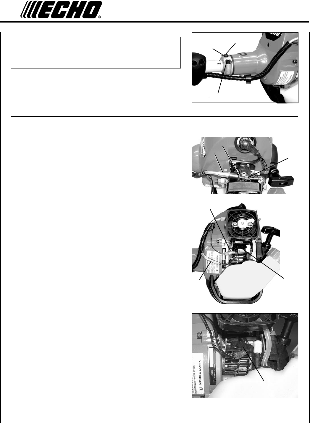
6. Route throttle linkage and ignition lead assembly along shaft and
clip as shown.
B
B
t h r o t t l e l I n k a g e a n d I g nItIo n l e a d s
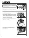
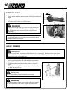
1. Close choke and remove air lter cover.
2. Place throttle linkage (C) through adjustment xture (D) and install
wire end into large carburetor throttle swivel hole (E). Check
throttle for freedom of movement and that wide open throttle / low
idle extremes are adjusted properly. The throttle linkage must be
adjusted by moving the adjustment xture (D). Consult with your
Echo Dealer for correct adjustment procedure.
3. Connect 2 ignition stop leads (F, G) from throttle cable tubing to 2
ignition leads (F, G) on engine.
4. Secure ignition leads against engine housing with clip (H).
5. Install air lter and cover.
C
D
F
G
H
E
A
H
NOTE
Gear Housing must be aligned properly with engine. Aligning cen-
ter locating hole in driveshaft housing with center drive shaft bolt
(A) provides correct alignment.