


5
RaceAmerica Model 3220 Timer SBD
SET-UP STEPS - 3220 SERIES
STEP 1 -
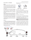
Familiarize yourself with the components pictured
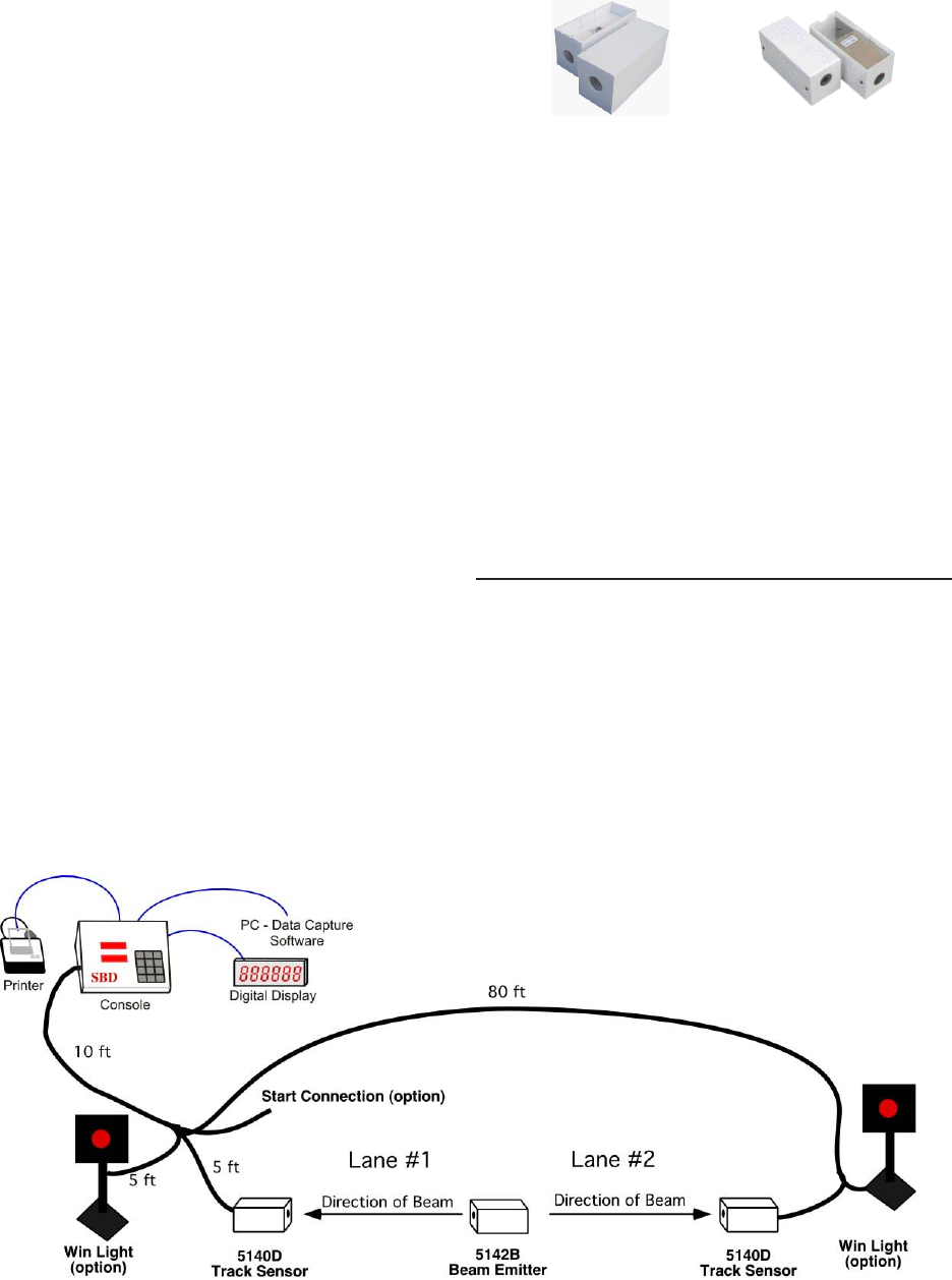
in this manual and how they interconnect. The
Track Sensor Interconnect Cable is configured
for connection between the a Sensors, Win Lights
and timer console at the finish line with a tail for
a Start Sensor.
All connectors are keyed for proper orientation.
The 12VDC battery is connected with the RED
alligator clip to plus (+) terminal of the battery
and the BLACK alligator clip to (-) terminal of
the battery.
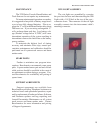
The free standing, battery powered Model 5042
IR Beam Emitter is placed on the centerline of the
track at the finish line and the Model 5140 IR Track
Sensors are placed on the outsides at the finish
line. The Track Sensor units are interchangeable
with each other. The Track Sensor Cable is keyed
to match the Lane 1 and Lane 2 track sensor
positions and marked at the end of the cable (see
cable diagram)
STEP 2 -
Identify the emitter/sensor placement at the
finish line. The lane width should be set between
four (4) and fifty (50) feet. To help in determining
initial Beam Emitter to Track Sensor alignment in
larger track widths, use a string stretched between
the beam emitter and track sensor or eyeball a
straight line between units.
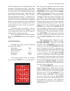
STEP 3 -
Layout the Track Sensor Interconnect Cables
on the track site (see cable diagram). The large
round connector connects to the console and the
two smaller connectors (RJ11) connect to the
Track Sensors at the finish line as indicated on the
cable near the RJ11 connector. Install the Emit-
ter and Sensors in the Foam Stands; connect the
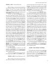
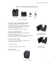
Model 5042 - IR Beam Emitter
The unit contains two Emitter units facing opposite
directions, powered by 4 ‘C’ batteries. When
connected to the batteries, the Emitter is ON.
Place the battery pack in the bottom of the Foam
Stand.
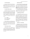
Model 5140 - IR Track Sensor
Note cable connector is located in the side facing
away from the track. All Track Sensor are fully
interchangeable with one another. Track Sensor
is pictured both top and bottom sides up.
Model 5042
IR Beam Emitter
Model 5140
IR Track Sensor
Picture shows one unit from the top and one unit
from the bottom.