


6
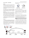
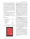
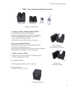
RaceAmerica Model 3220 Timer SBD
The Emitter throws a spot light like beam of infrared light; the Sensor should be aligned near the center
of the beam for optimal reception and alignment.
Sensor
Emitter
Interconnect Cable to the Timer Console and the
Track Sensors through the opening in the back of
the Foam Stand. If adding the ET option, see in-
structions for this option in the options section.
STEP 4 -
Cable tails are available to connect optional
Win Lights and Elapsed Time (ET) detection if
available. Install other purchased options per
the instructions in their respective section and
manuals.
STEP 5 -
Connect the RED (+) and BLACK (-) alliga-
tor clips to the 12VDC battery and you’re ready
to begin.
POWER ON/SELF-TEST
Connecting the 12VDC battery to the System
Console places the RaceAmerica 3220 Series
Timer into a self-test of the microprocessor cir-
cuitry and the LED (Light Emitting Diode) display
. This is an internal test as well as a visual check
of the LED display. The LED Displays progres-
sively sequence the digit ‘8’ through each segment
of all digits and then progressively turns them off;
then the upper display shows [LAnE 1] (and il-
luminates the Lane 1 Win Light if it is connected);
then the display shows [LAnE 2] (and illuminates
the Lane 2 Win Light if it is connected); finally,
the upper console display shows the product model
number [ 3220 ] and the lower display shows the
code revision level [C.00.0 ] contained within the
microprocessor.
ALIGNMENT MODE
All RaceAmerica timing systems have an
alignment mode. This is very useful for verifying
correct Emitter/Sensor alignment. After the track
layout has been determined and the Sensors and
Emitters placed in the proper positions, press the
[5] ALIGN key to enter alignment mode. The LED
Display shows [ALIgn] in the upper display and
briefly [-S-1-2] in the lower display. The digits
indicate Start, Lane 1, Lane 2 respectively. The
Status Display then changes each digit to a zero for
each sensor being monitored [-0-0-0]. If the Beam
Emitter and Track Sensor are operating properly
and aligned, the ‘0’ digit will not change. If the
Beam Emitter and Track Sensor are not properly
aligned, the 0 digit for each emitter/sensor pair will
count slowly if slightly out of alignment or con-
tinuously if they are not functioning properly or
way out of alignment. Once the emitter/sensor pair
are aligned properly, the digit will stop counting.
If the alignment is off a little or intermittent, the
digit for that emitter/sensor pair will count when
they float out of alignment. Remember, the Beam
Emitters and Track Sensors operate on a ‘Line-
of-Sight’ concept and may require shims if they
are installed on a surface with a crown. Leaves,
people, and other debris will also break the beams
and could give false signals, so keep everyone and
everything clear of the Beam Emitters and Track
Sensors during racing activity.
To maximize the alignment of the emitter/
sensor pairs, it is suggested to rotate the Beam
Emitter slowly left and right until the alignment
for that pair begins to count. This technique
will determine the maximum lateral detection
angle. Rotating the Beam Emitter up and down