


www.desatech.com
5122393-01A
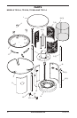
Hardware packet contains the following items
shown on pages 12 through 14:
Electronic Ignitor (1), Ignitor Wire (1), Ground
Wire (1), Knob (1), Propane Tank Retention
Chain (1), Retention Hook (2), and AA Bat-
tery (1).
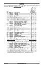
Parts are referenced by designated letter
throughout assembly instructions. Hardware
packet contains the following (quantity used
in parenthesis):
Description Part Number
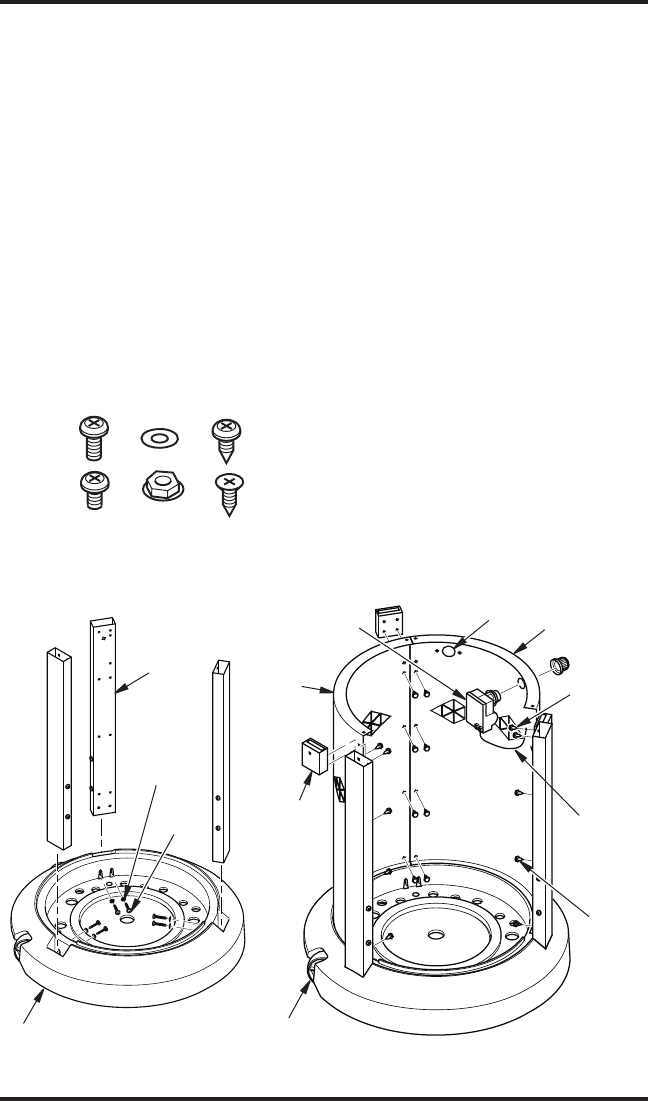
A 1" Screw (6) 119619-04
B 5 mm Washer (6) 119600-02
C 3/8" Screw (53) 119620-02
D 3/8" Machine Screw (9) 119742-01
E 10 mm Hex Nut (6) 119743-01
F 7/10" Self Tapping Screw (9) 121584-01
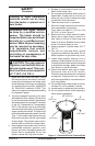
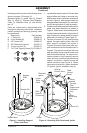
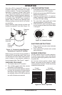
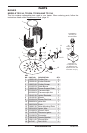
Figure 3 - Installing Support
Pillars into Base
Support
Pillar
Heater Base
ASSEMBLY
Continued
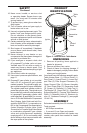
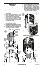
Figure 4 - Attaching Side Panels and Ignitor
Lower
Table
Panel
Wheel
Screw
(A)
Electronic
Ignitor
Hole for
Control Valve
Pillar
Support
Connector
Table
Control
Panel
Screw
Installs
Through
Pillar
Support and
Connector
Only
1. Locate table heater base and 3 lower table
support pillars with holes on one side only.
Making sure holes in pillars are oriented as
shown in Figure 3, slide support pillars into
base and attach with screws (A) and wash-
ers (B) through bottom 2 holes as shown.
2. Position lower table panel and table control
panel onto base assembly as shown in
Figure 4. Make certain lower table panel is
on side of base with wheels. Using bottom 3
sets of holes only, attach panels to support
pillars with 12 screws (C) (see Figure 4).
3. Top sets of screws (C) will insert through
panels, through support pillars, then into
pillar support connectors as shown in
Figure 4 (6 screws). Make sure pillar sup-
port connectors are oriented as shown in
Figure 4. The side of connectors with one
hole should be facing outside heater and
hole should be at the top. For support con-
nectors closest to front opening, second
screw will only install through panels and
support connectors. Second screw will
secure connector (see Figure 4). Attach
ignitor ground wire with 1 screw as shown
in Figure 4 (ignitor installed in step 4).
Washer (B)
Ignitor
Grounding
Wire
A B C
E
D
F
Screw (C)