


Page 21
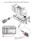
Assembly Instructions
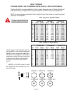
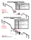
Preparation: Remove any loader brackets from the tractor. The
tractors duals must be set to 120” wheel spacing.
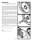
1. Remove every other lug bolt on the tractor’s dual, and replace
them with the special spacer Stud Bolts included with the SideQuest
hardware as shown in VIEW A. (Note: Only when replacing stud
bolts on a JD 7000 Series Tractor, the existing washers MUST be
used). After all of the removed lug bolts are replaced, remove the
rest of the tractor’s lug bolts and replace them with the SideQuest
stud bolts. Torque the SideQuest stud bolts to tractor manufacturer’s
specifications.
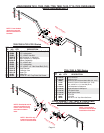
2. Bolt the Hub Spacer to the SideQuest stud bolts as shown in
VIEW B. Use ten 7/8”-UNF x 2” hex head bolts and ten 7/8” lockwashers.
Then bolt the Hub/Spindle Assembly to the Hub Spacer. Use eight 5/
8”-UNF x 2” hex head bolts and lockwashers to bolt the Hub/Spindle
Assembly to the Hub Spacer. Torque all bolts to the specifications
found earlier in the manual.
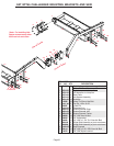
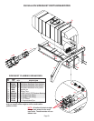
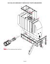
3. Mount the Left and Right Base Plates to the tractor’s frame. All Base
Plates will mount between the tractors cab and front wheels to existing
holes in the tractors frame. All tractors’ mounting brackets can be viewed
on pages 14-16.
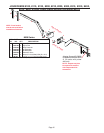
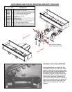
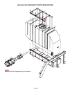
4. Mount the Tank Holder with Tank, and Tank Hold Downs. Before
mounting, decide which height setting is desirable. There are two height
settings. Slide the Tank holder over the spindle as shown in VIEW C.
Make sure the arrow on the end of the spindle is always pointing up as
shown. Use the bottom hole for a higher height setting, and use the
top hole for a lower height setting. Slide the tank holder in until there is
a spacing of approximately 2” between the tire and the Tank Holder.
Use four 1/2”-UNC x 1 1/4” set screws to hold the spindle in place.
Turn the set screws into the threaded inserts on the outside of the tube
the spindle has been placed in.
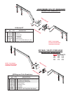
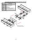
5. Next bolt the Mounting Extension Arm to the Tank Holder. Use four 1/
2”-UNC x 1 3/4” hex head bolts, four 1/2” lockwashers, and four 1/2”
hex nuts.
6. Repeat same instructions for the opposite side.
VIEW A
13
VIEW B
22
17
19
1
4
24
VIEW C
1
23
23
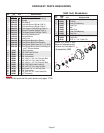
NOTE:
View A, B, & C use parts list on next page.