


34 se c t i O n 6— Ma i n t e n a n c e & ad j u s t M e n t s
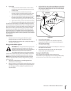
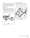
Loosen the inner jam nuts at the rear left and right of the 2.
the rear outer jam nut to raise the deck or loosen the rear
outer jam nut to lower the rear of the deck.
4.
out of the threaded rod.
Tighten both inner jam nuts to secure the deck adjustment.5.
6.
the left rear linkage if the rear of the deck was raised by
adjusting the jam nuts on the eyebolt. Loosen the jam nuts
In many cases it will be necessary to adjust deck height 7.
using both eyebolt adjustments and pitch adjustment
to achieve the correct blade-to-ground heights. If you
remember that the front right blade tip adjustment is fixed
and you level to that height, adjusting the decks will be
simplified.
5.
cut does not match the height of cut indicator. A final
adjustment may be made by lowering or raising the height
of cut link accordingly. To raise the deck: remove the
shoulder bolt mounting the height of cut link to the lift
handle and reassemble the shoulder bolt in the lowest of
the three holes. To lower the deck: remove the shoulder
bolts mounting the height of cut link, flip the height of cut
link around and reassemble the shoulder bolts in the top of
the set of three holes and the bottom hole.
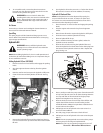
Adjusting the Deck Corner Gauge Wheels
WARNING! Keep hands and feet away from the
discharge opening of the cutting deck.
NOTE: The deck gauge wheels are an anti-scalp feature of the
deck and are not designed to support the weight of the cutting
deck.
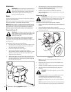
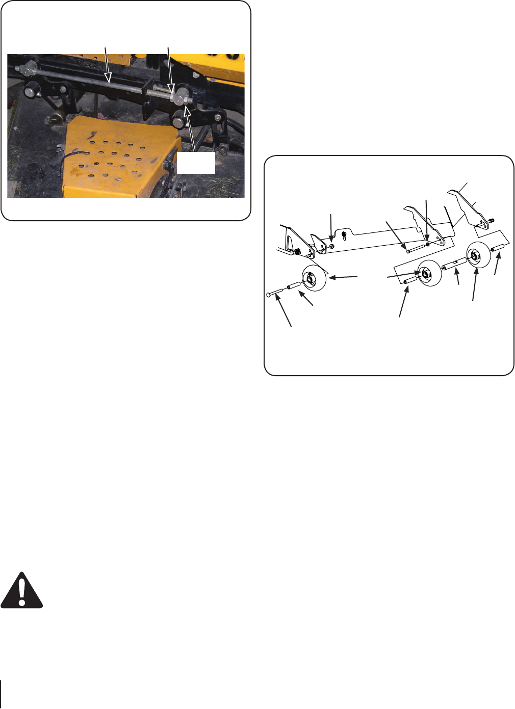
Inner
Jam Nut
Outer
Jam Nut
Horizontal
Threaded Rod
Figure 6-8
deck gauge wheel position should be approximately ⁄ to ⁄
above the ground when the deck is set in the desired height
setting.
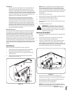
Using the power implement lift, set the deck in the desired
height setting, then check the gauge wheel distance from the
ground below. If necessary, adjust as follows:
Visually check the distance between the front gauge
wheels and the ground. If the gauge wheels are near or
touching the ground, they should be raised. If more than
⁄
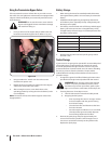
Remove the lock nut securing one of the outer front gauge 2.
wheel shoulder screws to the deck. Remove the gauge
Insert the shoulder screw into the one of three index holes
in the front gauge wheel bracket and spacer that will give
the gauge wheel a ⁄ to ⁄
Note the index hole of the just adjusted wheel, and adjust 4.
the other gauge wheels into the respective index holes of
the other gauge wheel brackets on the deck.
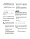
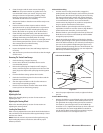
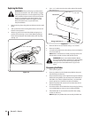
Adjusting the Center Gauge Wheels
Adjust the center gauge wheels to the same height as the outer
washer, the wheel bracket, the spacer and wheel and then the
center shaft.
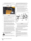
Adjusting the Rear Rollers
The rear rollers help prevent the scalping of high spots and
uneven terrain across the center section of the deck. The rollers
will increase the striping effect left behind the mower. This
positioning of the rear roller will also help to filter the mulched
grass clippings into the turf.
NOTE: Roller should not be lowered if the cut height is set at 2-⁄
or lower.
Carriage
Bolt
Spacer
Gauge
Wheel
Spacer
Spacer
Shaft
Gauge
Wheel
Nut
Hex
Screw
Washer
Figure 6-9