


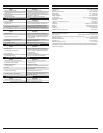
CAUSE ACTION
Empty fuel tank Fill fuel tank with fuel
Primer bulb wasn't pressed enough Press primer bulb fully and slowly 10 times
Old fuel Drain gas tank and add fresh fuel
Fouled spark plug Replace or clean the spark plug
Plugged spark arrestor Clean or replace spark arrestor
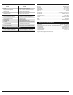
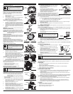
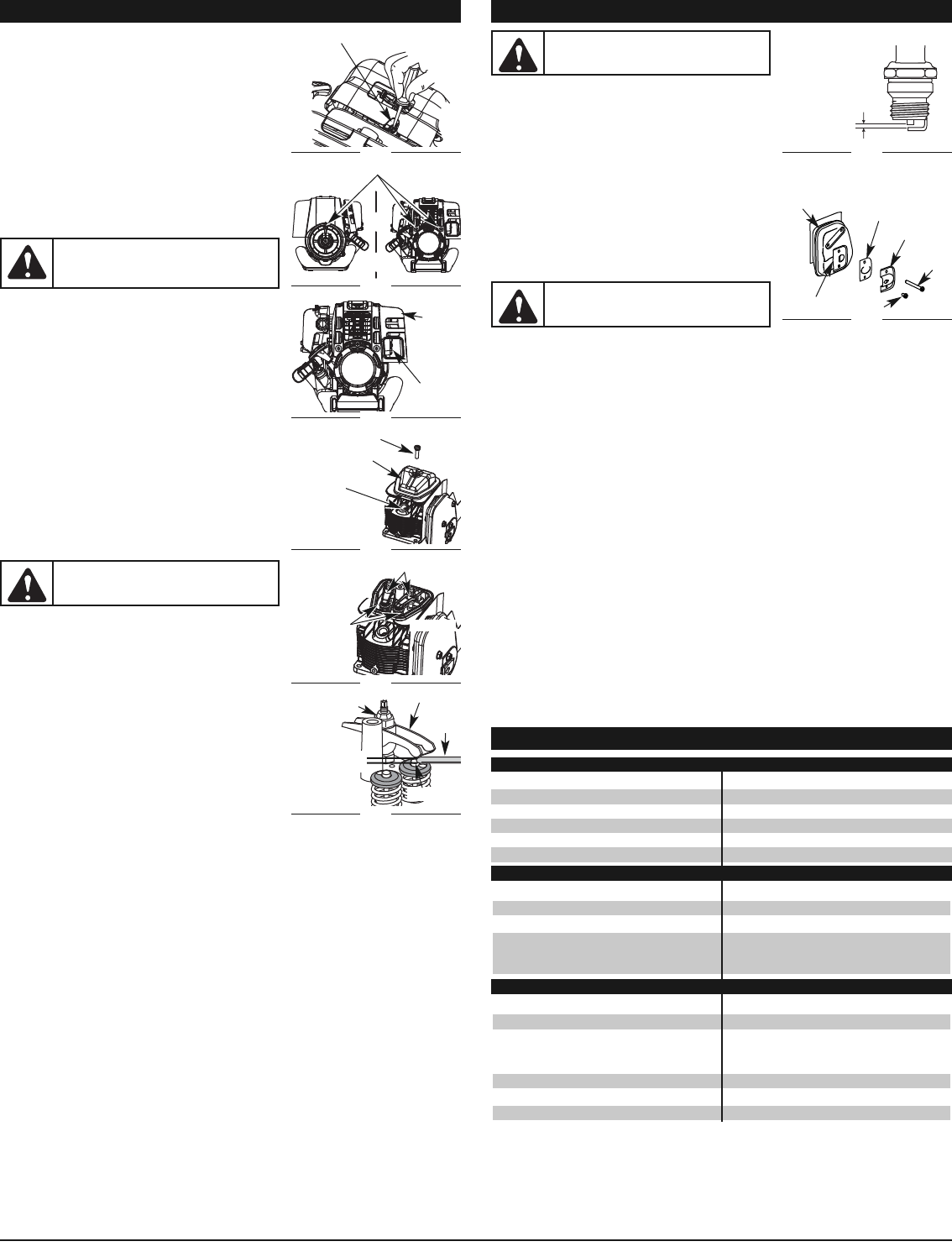
3. Replace cracked, fouled or dirty spark plug. Set the air gap
at 0.025 in. (0.635 mm) using a feeler gauge (Fig. 37).
4. Install a correctly-gapped spark plug in the cylinder head.
Turn the 5/8 in. socket clockwise until snug.
If using a torque wrench torque to:110-120 in.•lb. (12.3-13.5 N•m)
Do not over tighten.
SPARK ARRESTOR MAINTENANCE
1. Remove the engine cover. See Rocker Arm Clearance.
2. With a flat blade screwdriver or Torx T-20 bit and a T-25 bit, remove the screws attaching the spark
arrestor diverter to the muffler (Fig. 38).
3. Pull the tab on the spark arrestor cover out of the muffler.
Remove the spark arrestor cover.
4.
Remove the spark arrestor screen from the spark arrestor cover.
5. Clean the spark arrestor screen with a wire brush or replace it.
6.
Reinstall the spark arrestor screen, spark arrestor cover and screw.
CLEANING
Use a small brush to clean off the outside of the unit. Do not use strong detergents. Household cleaners
that contain aromatic oils such as pine and lemon, and solvents such as kerosene, can damage plastic
housing or handle. Wipe off any moisture with a soft cloth.
STORAGE
• Never store the unit with fuel in the tank where fumes may reach an open flame or spark.
• Allow the engine to cool before storing.
• Lock up the unit to prevent unauthorized use or damage.
• Store the unit in a dry, well-ventilated area.
• Store the unit out of the reach of children.
LONG TERM STORAGE
1. Drain all gasoline from the gas tank into a container. Do not use gas that has been stored for more
than 60 days. Dispose of the old gasoline in accordance to Federal, State, and Local regulations.
2. Start the engine and allow it to run until it stalls. This ensures that all gasoline has been drained
from the carburetor.
3. Allow the engine to cool. Remove the spark plug and put 5 drops of high quality motor oil into the
cylinder. Pull the starter rope slowly to distribute the oil. Reinstall the spark plug.
NOTE: Remove the spark plug and drain all of the oil from the cylinder before attempting to start the
trimmer after storage.
4. Change the oil, referring to Changing the Oil. Dispose of the old oil in accordance to Federal, State
and Local regulations.
5. Thoroughly clean the unit and inspect for any loose or damaged parts. Repair or replace damaged
parts and tighten loose screws, nuts or bolts. The unit is ready for storage.
TRANSPORTING
• Allow the engine to cool before transporting.
• Secure the unit while transporting.
• Drain the gas tank before transporting.
• Tighten gas cap before transporting.
MAINTENANCE AND REPAIR INSTRUCTIONS
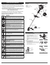
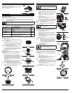
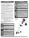
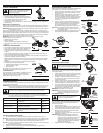
CARBURETOR ADJUSTMENT
The idle speed of the engine is adjustable. An idle adjustment screw is
between the air filter cover and the engine starter housing (Fig. 31).
NOTE: Careless adjustments can seriously damage your
unit. An authorized service dealer should make
carburetor adjustments.
Check Fuel
Old fuel is usually the reason for improper unit performance. Drain
and refill the tank with fresh fuel prior to making any adjustments.
Refer to Oil and Fuel Information.
Clean Air Filter
The condition of the air filter is important to the operation of the
unit. A dirty air filter will restrict air flow. This is often mistaken for
an out of adjustment carburetor. Check the condition of the air
filter before adjusting the idle speed screw. Refer to Air Filter
Maintenance.
Adjust Idle Speed Screw
If, after checking the fuel and cleaning the air filter, the engine still
will not idle, adjust the idle speed screw as follows:
1. Start the engine and let it run at a high idle for a minute to
warm up. Refer to Starting/Stopping Instructions.
2. Release the throttle trigger and let the engine idle. If the
engine stops, insert a small phillips or flat blade screwdriver
into the hole in the air filter/muffler cover (Fig. 31). Turn the
idle speed screw in, clockwise, 1/8 of a turn at a time (as
needed) until the engine idles smoothly.
NOTE: The cutting attachment should not rotate when the
engine idles.
3. If the cutting attachment rotates when the engine idles, turn
the idle speed screw counterclockwise 1/8 of a turn at a
time (as needed), to reduce idle speed.
Checking the fuel, cleaning the air filter, and adjusting the idle
speed should solve most engine problems. If not and all of the
following are true:
• the engine will not idle
• the engine hesitates or stalls on acceleration
• there is a loss of engine power
Have the carburetor adjusted by an authorized service dealer.
ROCKER ARM CLEARANCE
This requires disassembly of the engine. If you feel unsure or
unqualified to perform this, take the unit to an authorized service
center.
NOTE: Inspect the valve to rocker arm clearance with a
feeler gauge after the first 25 hours of operation and
then every 25 hours of operation thereafter.
• The engine must be cold when checking or adjusting the valve
clearance.
• This task should be performed inside in a clean, dust free area.
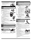
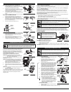
1. Remove the two (2) screws on back of the engine cover and
the one on the front of the engine cover with a Flat-head or
T-25 Torx screwdriver (Fig. 32).
2. Remove the engine cover (Fig. 33).
3. Disconnect the spark plug wire.
4. Clean dirt from around the spark plug. Remove the spark
plug from the cylinder head by turning a 5/8 in. socket
counterclockwise.
5. Clean dirt from around the rocker arm cover. Remove the
screw holding the rocker arm cover with a large flat blade screwdriver or Torx T-25 bit (Fig. 34).
Remove the rocker arm cover and gasket.
6. Pull the starter rope slowly to bring the piston to the top of its travel, (known as top dead center).
Check that:
• The piston is at the top of its travel while looking in the spark plug hole (Fig. 34)
• Both rocker arms move freely, and both valves are closed
If these statements are not true, repeat this step.
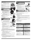
7. Slide the feeler gauge between the rocker arm and the valve return spring. Measure the clearance
between the valve stem and rocker arm (Fig. 36). Measure both the intake and exhaust valves.
The recommended clearance for both intake and exhaust is .003 – .006 in. (.076 – 0.152 mm). Use a
standard automotive .005 in. (0.127 mm) feeler gauge. The feeler gauge should slide between the rocker
arm and valve stem with a slight amount of resistance, without binding. Figure 35 and 36 show how to
measure the clearance.
8. If the clearance is not within specification:
a. Turn the adjusting nut using a 5/16 inch (8 mm) wrench or nut driver (Fig. 36).
• To increase clearance, turn the adjusting nut counterclockwise.
• To decrease clearance, turn the adjusting nut clockwise.
b. Recheck both clearances, and adjust as necessary.
9. Reinstall the rocker arm cover using a new gasket. Torque the screw to 20–30 in•lb (2.2–3.4 N•m).
10. Check the spark plug and reinstall. See Replacing the Spark Plug.
11. Replace the spark plug wire.
12. Reinstall the engine cover. Check alignment of the cover before tightening the screws. Tighten screws.
REPLACING THE SPARK PLUG
Use a replacement part number 753-05255 spark plug. The correct air gap is 0.025 in. (0.635 mm).
Remove the plug after every 25 hours of operation and check its condition.
1. Stop the engine and allow it to cool. Remove the two (2) screws on back of the engine cover and
the one on the front of the engine cover with a Flat-head or T-25 Torx screwdriver (Fig. 32).
2. Grasp the plug wire firmly and pull the cap from the spark plug.
3. Clean dirt from around the spark plug. Remove the spark plug from the cylinder head by turning a
5/8 in. socket counterclockwise.
Muffler
Fig. 38
Slot
Fig. 37
0.025 in.
(0.635 mm.)
Spark Arrestor
Screen
Diverter
T-25
Screw
T-20 Screw
MAINTENANCE AND REPAIR INSTRUCTIONS
WARNING:
To avoid serious personal injury,
always turn the unit off and allow it to cool
before you clean or service it.
WARNING:
To avoid serious personal injury,
always turn the unit off and allow it to cool
before you clean or service it.
WARNING:
Do not sand blast, scrape or clean
electrodes. Grit in the engine could damage the
cylinder.
TROUBLESHOOTING
CAUSE ACTION
Air filter is plugged Replace or clean the air filter
Old fuel Drain gas tank and add fresh fuel
Improper carburetor adjustment
Adjust according to the Carburetor Adjustments
section or take to an authorized service dealer
for an adjustment
CAUSE ACTION
Old fuel Drain gas tank and add fresh fuel
Improper carburetor adjustment
Adjust according to the Carburetor Adjustments
section or take to an authorized service dealer
for an adjustment
Cutting attachment bound with grass Stop the engine and clean the cutting attachment
Dirty air filter Clean or replace the air filter
Plugged spark arrestor Clean or replace spark arrestor
ENGINE WILL NOT START
ENGINE WILL NOT ACCELERATE
ENGINE WILL NOT IDLE
Idle Ajustment Screw
Fig. 31
Fig. 32
Fig. 33
Muffler
Rocker Arm Cover
Fig. 34
Screw
Adjusting Nuts
Fig. 35
INTAKE
Valve Stem
Fig. 36
Exhaust
Adjusting Nut
Feeler
Gauge
Rocker Arm
Rocker Arms
EXHAUST
Remove Screws
Engine
Cover
6
Spark Plug
Hole
WARNING:
The cutting attachment may spin
during idle speed adjustments. Wear protective
clothing and observe all safety instructions to
prevent serious personal injury.
0.003–0.006 in.
(0.076–0.152 mm)