


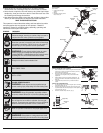
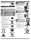
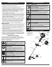
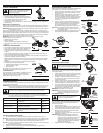
DECORATIVE TRIMMING
Decorative trimming is accomplished by removing all vegetation
around trees, posts, fences and more.
Rotate the whole unit so that the cutting attachment is at a 30°
angle to the ground (Fig. 15).
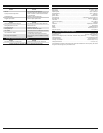
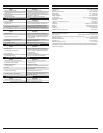
MAINTENANCE AND REPAIR INSTRUCTIONS
MAINTENANCE SCHEDULE
Perform these required maintenance procedures at the frequency stated in the table. These procedures
should also be a part of any seasonal tune-up.
NOTE: Some maintenance procedures may require special tools or skills. If you are unsure about
these procedures take your unit to any non-road engine repair establishment, individual or
authorized service dealer.
NOTE: Maintenance, replacement, or repair of the emission control devices and system may be
performed by any non-road engine repair establishment, individual or authorized service dealer.
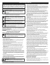
WARNING:
To prevent serious injury, never perform maintenance or repairs with unit
running. Always service and repair a cool unit. Disconnect the spark plug wire to ensure
that the unit cannot start.
MAINTENANCE AND REPAIR INSTRUCTIONS
FREQUENCY MAINTENANCE REQUIRED SEE
Before starting engine Fill fuel tank with fresh fuel
Check oil
p. 4
p. 5
Every 10 hours Clean air filter p. 5
Every 25 hours
Every 40 hours
Change oil
Clean spark arrestor and change oil
p. 5
p. 6
Every 25 hours Check rocker arm to valve clearance and adjust
Check spark plug condition and gap
p. 6
p. 6
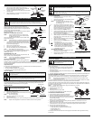
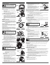
REMOVING THE OLD LINE
1. Firmly press in on the tabs that are on each side of the
cutting head. (Fig. 16)
NOTE: May find it easier to press in and then up on one tab
at a time.
2. Remove the cap either by letting it pop off or a slight wiggle
of the cap may be required and pull out the spool (Fig. 17)
3. Unwind the old line from the spool and remove it from the
center hole of the spool. (Fig. 18)
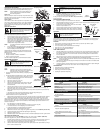
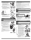
NOTE: When placing the spool back into the outer spool,
make sure the side with the L is facing up.
4. Place the spool back into the outer spool cover (Fig. 17)
5. Replace the cutting head cap and press down firmly until
both tabs snap back into place. (Fig. 19)
LINE INSTALLATION
Always use original equipment manufacturer 0.095 in. (2.41 mm)
replacement line. Other types of line may make the engine
overheat or fail.
1. Align the arrows on the cutting head knob with the
outerspool eyelets, if they are not already.(Fig. 20)
2. Using 10.5 ft. (3.2 m) of 0.095 in. (2.41 mm) replacement
line push an end of the line through one of the eyelets until
it protrudes through the opposite side. Continue pushing or
pulling the line until the line is evenly distributed, so
approximately 5 ft. (1.5 m) is visible from both sides of the
cutting head.(Fig. 21)
3.
Hold the cutting head knob and turn the cutting head clockwise
to wind the line around the spool until 5 in. (12.7 cm) is
protruding from each side of the cutting head.(Fig. 22)
NOTE: If winding the line from a large spool of line, cut the line
from the spool so that it measures 5” from the eyelet.
4. Start the unit and bump the cutting head on the ground
until the desired cutting length is achieved.
OPERATING INSTRUCTIONS
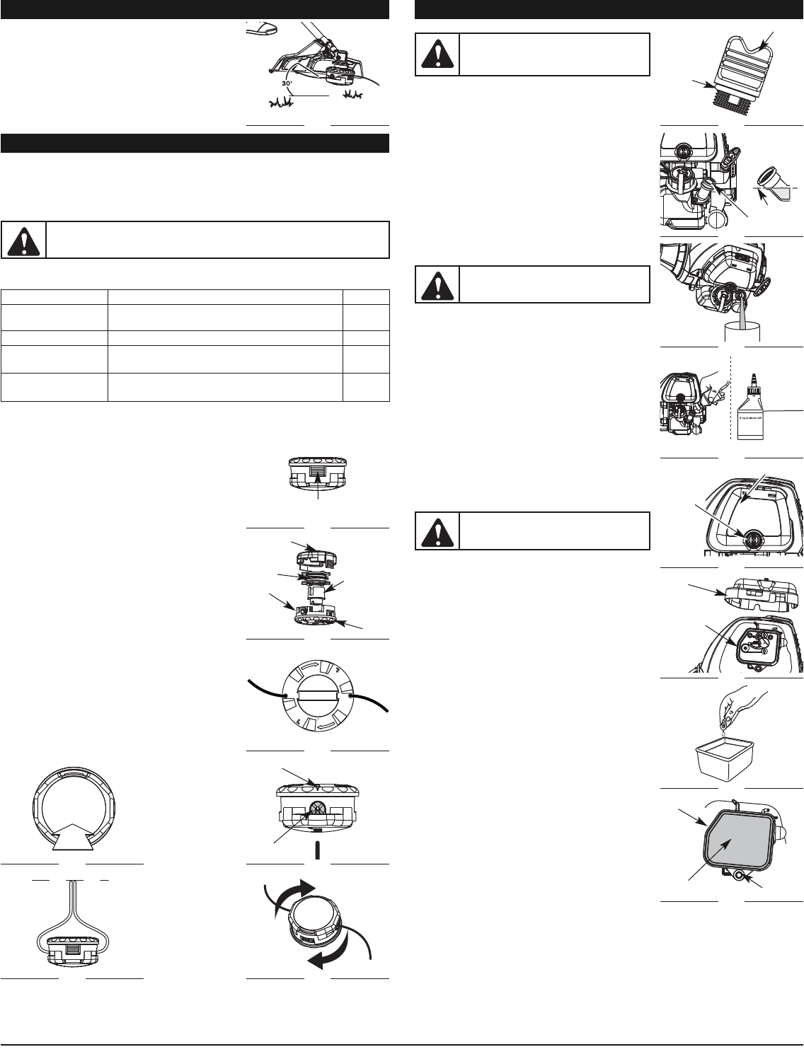
CHECKING THE OIL LEVEL
The importance of checking and maintaining the proper oil level in the
crankcase cannot be overemphasized. Check oil before each use:
1. Stop the engine and allow oil to drain into the crankcase.
2. Place the unit on a flat, level surface to get a proper oil level
reading.
3. Keep dirt, grass clippings and other debris out of the
engine. Clean the area around the oil fill plug before
removing it.
4. Remove the oil fill plug.
5. Check the oil level. Oil should be just to the bottom of the
threads of the oil fill hole. (Fig. 24).
6. If the level is low, add a small amount of oil to the oil fill hole
and recheck (Fig. 24). Repeat this procedure until the oil level
reaches the the bottom of the threads in the oil fill hole.
NOTE: Do not overfill the unit.
NOTE: Make sure the O-ring is in place on the oil fill plug
when checking and changing the oil (Fig. 23).
CHANGING THE OIL
For a new engine, change the oil after the first 25 hours of
operation. Change the oil while the engine is still warm. The oil will
flow freely and carry away more impurities.
1. Remove the oil fill plug.
2. Pour the oil out of the oil fill hole and into a container by
tipping the unit to the side (Fig. 25). Allow ample time for
complete drainage.
3. Wipe up any oil residue on the unit and clean up any oil that
may have spilled. Dispose of the oil according to Federal,
State and local regulations.
4. Refill the crankcase with 3.04 fluid ounce (90 ml) of SAE 30
SF, SG, SH oil.
NOTE: Use the bottle and spout saved from initial use to
measure the correct amount of oil. The top of the
label on the bottle measures approximately 3.4
ounces (100 ml) (Fig. 26). Check the level (Fig. 24). If
the level is low, add a small amount of oil and
recheck. Do not overfill (Fig. 24).
5. Replace the oil fill plug.
AIR FILTER MAINTENANCE
Cleaning the Air Filter
Clean the air filter every 10 hours of operation. It is an important
item to maintain. Failure to maintain your air filter properly can
result in poor performance or can cause permanent damage to
your engine.
1. Open the air filter cover by unscrewing the air filter screw
(Fig. 27).
2. Remove the air filter (Fig. 28).
3. Wash the filter in detergent and water (Fig. 29). Rinse the
filter thoroughly and allow it to dry.
4. Replace the air filter into the base plate (Fig. 30).
NOTE: If the unit is operated without the air filter, you will
VOID the warranty.
5. Reinstall the air filter cover. Position the hooks on the air filter
cover to the top of the back plate and lower the air filter cover
down so that the air filter screw aligns with the screw hole
on the back plate (Fig. 28).
6. Turn the air filter screw clockwise until the air filter screw is
tight (Fig. 27).
NOTE: Do not over tighten as this may strip the screw.
WARNING:
To prevent extensive engine wear
and damage to the unit, always maintain the
proper oil level in the crankcase. Never operate
the unit with a low oil level.
CAUTION:
Wear gloves to prevent injury
when handling the unit.
WARNING:
To avoid serious personal injury,
always turn the unit off and allow it to cool
before you clean or service it.
Fig. 15
Fig. 16
Fig. 17
Fig. 19
Fig. 18
Fig. 21
Fig. 20
Fig. 22
Fig. 23
O-Ring
Oil Fill Plug
Oil Fill Hole
Fig. 24
Fig. 25
Fill Level
Fig. 26
Add 1.4-1.5 Oz.
(41-44 ml)
Air Filter
Screw
Fig. 27
Air Filter Cover
Fig. 29
Air Filter
Fig. 30
Back Plate
Air Filter Cover
Fig. 28
Back Plate
5
Bump Cap
Spool
Spool Lock
Outer Spool
Oil Full Line
Knob
Arrow
Eyelet
Screw Hole
Tabs
PRESS