


Section 6 — Maintenance & adjuStMentS
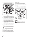
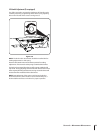
Steering Housing & Steering Shaft
The steering housing and steering shaft should be lubricated
after every 25 hour of operation. To access the lube fittings,
proceed as follows:
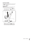
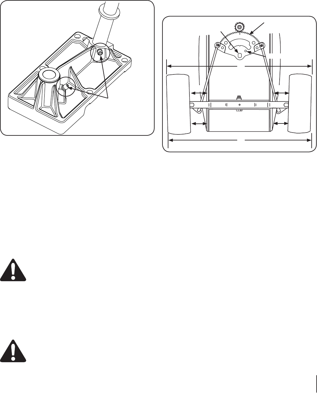
2. Locate the grease fitting for the steering housing and
steering shaft under the battery. See Figure 6-5.
Grease Fittings
Figure 6-5
an equivalent No. 2 multipurpose lithium grease, through
the grease fittings.
4. Close the tractor hood
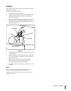
Deck Wheels
fitting. Lubricate with a No. 2 multi-purpose grease applied with a
grease gun after every 25 hours of tractor operation.
Pivot Points & Linkage
Lubricate all the pivot points on the drive system, parking brake
and lift linkage at least once a season with light oil.
Adjustments
WARNING! Shut the engine off, remove the
ignition key and engage the parking brake before
making adjustments. Protect your hands by using
heavy gloves when handling the blades.
NOTE:
information regarding tire pressure.
Seat Adjustment
Refer to the Assembly & Set-Up section of this manual for seat
adjustment instructions.
WARNING! Before operating the tractor, make
sure the seat is engaged in the seat-stop. Engage the
parking brake. Stand behind the machine and pull
back on seat until it clicks into place.
Parking Brake Adjustment
If the tractor does not come to a complete stop when the brake
roll with the parking brake applied (and the hydrostatic relief
valve open), the brake is in need of adjustment. See your Cub
Cadet dealer to have the brake adjusted.
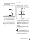
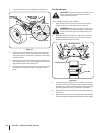
Wheel Alignment
The front wheels should toe-in approximately ⁄ to ⁄, as
measured across dimensions A and B. See Figure 6-6.
Centering Hole
Steering Gear
Centered
A
B
C C
D
D
Pivot Hole
Figure 6-6
Steering/Toe-in Adjustment
To adjust front wheel toe-in, proceed as follows:
Check the steering gear to ensure it is in the centered
position. The hole in the steering segment gear will align
with the hole in the steering housing (See Figure 6-6).
NOTE: A ⁄
assure the steering segment is centered.
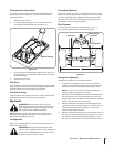
2. Mark the front horizontal diameter of both front wheels at
the same spot on each wheel-preferably the inner bead
flange of the wheel rims. Mark the rear horizontal diameter
of both front wheels in the same manner.
Measure the distance between the bottom edges of the
tractor frame channels and the marks on the front of each
wheel (See measurement D in Figure 6-6). These two
measurements should be equal.
4. Measure the distance between the frame and the marks on
the rear of each front wheel (See measurement C in Figure
6-6). Measurement D should be approximately ⁄- to ⁄-
inch less than measurement C on each side of the tractor.
21