


5
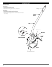
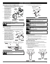
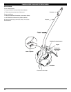
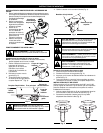
INSTALLING CUTTING ATTACHMENT SHIELD
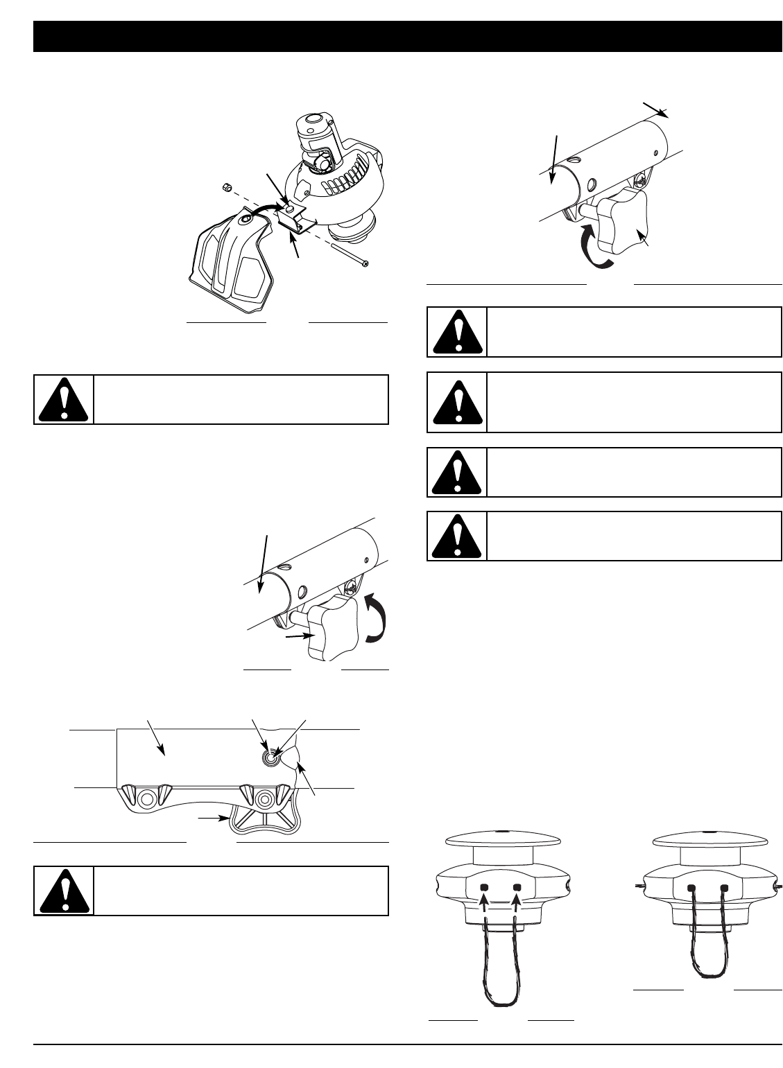
1. Place the narrow end of the cutting attachment shield over the
shield bracket and position it so that the circular cut-out slips
over the guard assembly peg (Fig. 1).
2. Place the locking nut
into the hexagonal hole
on the left side of the
guard and hold in place.
3. Insert the assembly
screw into the hole on
the right side of the
guard and screw it
into the nut on the left
side using a Phillips-
head screwdriver.
4. Make sure the screw
is tight before
operating the unit.
Fig. 1
Guard
Assembly
Peg
Shield
Bracket
ASSEMBLY INSTRUCTIONS
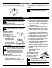
OPERATING THE RAPID-LINK™ SYSTEM
To Install Attachments
NOTE: To make installation easier, place the unit on the ground
or on a workbench.
1. Remove the hanger from the top of the shaft housing by
depressing the release button and pulling the hanger off
the end of the attachment.
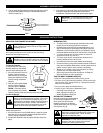
2. Turn the knob counterclockwise
to loosen the coupler (Fig. 2).
3. While firmly holding the
attachment, push it straight into
the coupler until the release
button (Fig. 3) snaps into the
primary hole (Fig. 3). The
primary hole is on the opposite
side of the coupler from the
knob (Fig. 3). Align the release
button with the Guide Recess
(Fig. 3) to help installation.
Knob
Coupler
Fig. 2
Fig. 3
Rapid-Link™ Coupler
Release Button
Guide
Recess
Knob
Primary Hole
CAUTION: Lock the release button in the primary
hole (Fig. 3) and securely tighten the knob before
operating this unit.
Attachment
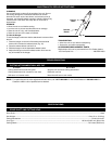
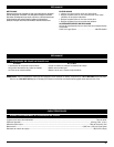
4. Turn the knob clockwise to tighten (Fig. 4).
CAUTION: These attachments are to be snapped
into the primary hole only. Using the wrong hole could
lead to personal injury or damage to the unit.
CAUTION: Before operating this unit, be sure
that the release button is fully snapped into the
primary hole (Fig. 3), and that the knob (Fig. 4) is
securely tightened.
Fig. 4
Knob
Attachment
Upper Shaft Boom
Coupler
WARNING: Never use metal-reinforced line, wire,
chain, or rope. These can break off and become
dangerous projectiles.
WARNING: Always use the correct line length
when installing trimming line on the unit.
To Remove Attachments
1. Make sure the unit is turned completely off.
2. Turn the knob counterclockwise to loosen the coupler (Fig.
2).
3. Press and hold the release button (Fig. 3).
4. While firmly holding the upper shaft boom (Fig. 4), pull the
attachment out of the coupler.
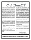
INSTALLING FIXED LINE
Always use original equipment manufacturer 0.105 inch
(2.667 mm) replacement line. Lines other than those specified
may make the engine overheat or fail.
To install the trimming line:
1. Insert each end of the replace-ment line into the holes on
either side of retention hook (Fig. 5).
2. Push the ends through until they stick out of the sides of
the head (Fig. 6).
Fig. 5
Fig. 6
WARNING: Do NOT use this attachment with an
electric-powered product.