


6
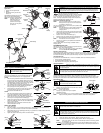
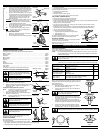
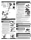
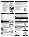
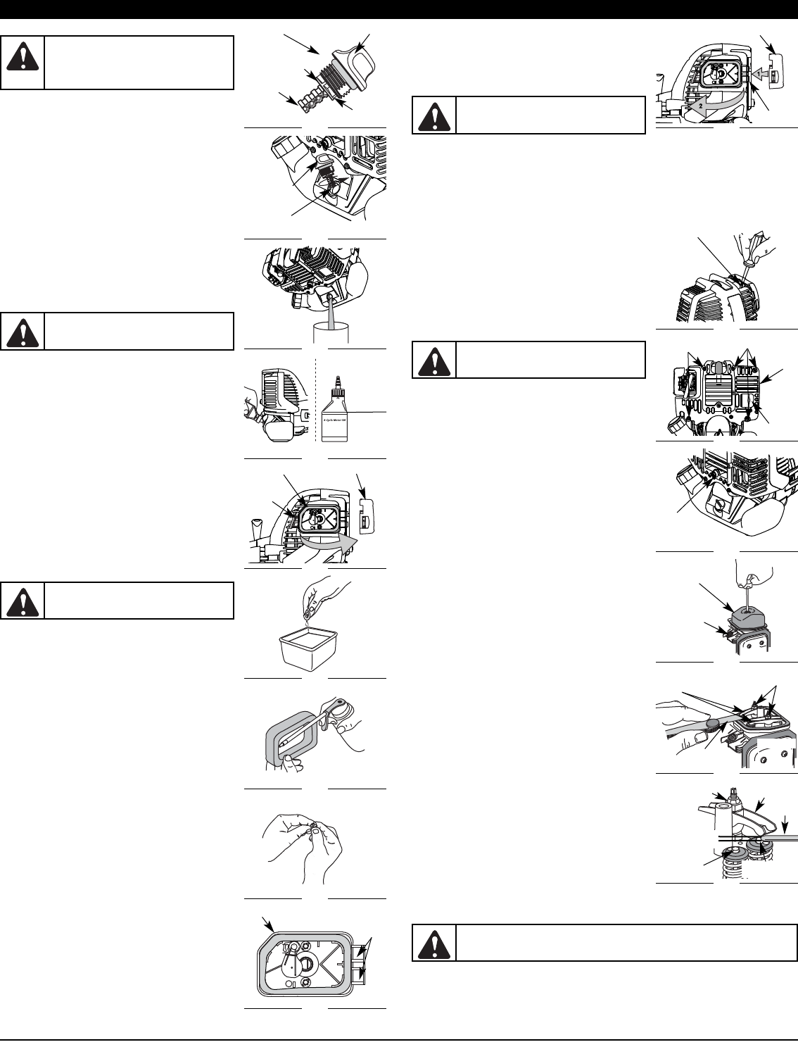
CHECKING THE OIL LEVEL
The importance of checking and maintaining the proper oil level in
the crankcase cannot be overemphasized. Check oil before each
use:
1. Stop the engine and allow oil to drain into the crankcase.
2. Place the unit on a flat, level surface to get a proper oil
level reading.
3. Keep dirt, grass clippings and other debris out of the
engine. Clean the area around the oil fill plug/dipstick
before removing it.
4. Remove the oil fill plug/dipstick and wipe off oil. Reinsert it
all the way back in.
5. Remove the oil fill plug/dipstick and check the oil level. Oil
should be up to the top of the dipstick (Fig. 22).
6. If the level is low, add a small amount of oil to the oil fill
hole and recheck (Fig. 23). Repeat this procedure until the
oil level reaches the top of the dipstick.
NOTE: Do not overfill the unit.
NOTE: Make sure the O-ring is in place on the oil fill
plug/dipstick when checking and changing the oil
(Fig. 22).
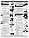
CHANGING THE OIL
For a new engine, change the oil after the first 10 hours of
operation. Change the oil while the engine is still warm. The oil will
flow freely and carry away more impurities.
1. Unplug spark plug boot to prevent accidental starting.
2. Remove the oil fill plug/dipstick.
3. Pour the oil out of the oil fill hole and into a container by
tipping the unit to a vertical position (Fig. 24). Allow ample
time for complete drainage.
4. Wipe up any oil residue on the unit and clean up any oil
that may have spilled. Dispose of the oil according to
Federal, State and local regulations.
5. Refill the crankcase with 3.04 fluid ounce (90 ml) of SAE 30
SF, SG, SH oil.
NOTE: Use the bottle and spout saved from initial use to
measure the correct amount of oil. The top of the
label on the bottle measures approximately 3.4
ounces (100 ml) (Fig. 25). Check the level with the
dipstick. If the level is low, add a small amount of oil
and recheck. Do not overfill (Fig. 25).
6. Replace the oil fill plug/dipstick.
7. Reconnect the spark plug boot.
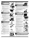
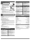
AIR FILTER MAINTENANCE
Cleaning the Air Filter
Clean and re-oil the air filter every 10 hours of operation. It is an
important item to maintain. Failure to maintain your air filter
properly can result in poor performance or can cause permanent
damage to your engine.
1. Open the air filter cover. Push the tab on the left side of the
cover inward. Then pull the air filter cover out and to the
right (Fig. 26).
NOTE: It may be necessary to remove the fuel cap to
completely remove the air filter cover.
2. Remove the air filter (Fig. 26).
3. Wash the filter in detergent and water (Fig. 27). Rinse the
filter thoroughly and allow it to dry.
4. Apply enough clean SAE 30 motor oil to lightly coat the
filter (Fig. 28).
5. Squeeze the filter to spread and remove excess oil (Fig. 29).
6. Replace the filter (Fig. 30).
NOTE: If the unit is operated without the air filter, you will
VOID the warranty.
7. Reinstall the air filter cover. Position the hooks on the right
side of the air filter cover into the slots at the right side of
the back plate (Fig. 31, no.1).
8. Swing the cover to the left until the tab on the air filter cover
snaps into place in the slot on the back plate (Fig. 31, no. 2).
CARBURETOR ADJUSTMENT
The idle speed of the engine is adjustable. An idle adjustment screw
is reached though a hole in the top of the engine cover (Fig. 32).
NOTE: Careless adjustments can seriously damage your
unit. An authorized service dealer should make
carburetor adjustments.
Check Fuel
Old fuel is usually the reason for improper unit performance. Drain
and refill the tank with fresh fuel prior to making any adjustments.
Refer to Oil and Fuel Information.
MAINTENANCE AND REPAIR INSTRUCTIONS
Clean Air Filter
The condition of the air filter is important to the operation of the
unit. A dirty air filter will restrict air flow. This is often mistaken for
an out of adjustment carburetor. Check the condition of the air
filter before adjusting the idle speed screw. Refer to Air Filter
Maintenance.
Adjust Idle Speed Screw
If, after checking the fuel and cleaning the air filter, the engine still will not idle, adjust the idle speed
screw as follows:
1. Start the engine and let it run at a high idle for a minute to warm up. Refer to Starting/Stopping
Instructions.
2. Release the throttle trigger and let the engine idle. If the engine stops, insert a small phillips or flat
blade screwdriver into the hole in the air filter/muffler cover (Fig. 32). Turn the idle speed screw in,
clockwise, 1/8 of a turn at a time (as needed) until the engine idles smoothly.
NOTE: The cutting attachment should not rotate when the engine idles.
3. If the cutting attachment rotates when the engine idles,
turn the idle speed screw counterclockwise 1/8 of a turn
at a time (as needed), to reduce idle speed.
Checking the fuel, cleaning the air filter, and adjusting the idle
speed should solve most engine problems. If not and all of the
following are true:
• the engine will not idle
• the engine hesitates or stalls on acceleration
• there is a loss of engine power
Have the carburetor adjusted by an authorized service dealer.
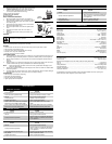
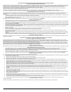
ROCKER ARM CLEARANCE
This requires disassembly of the engine. If you feel unsure or
unqualified to perform this, take the unit to an authorized service
center.
NOTE: Inspect the valve to rocker arm clearance with a
feeler gauge after the first 10 hours of operation and
then every 25 hours of operation thereafter.
• The engine must be cold when checking or adjusting the valve
clearance.
• This task should be performed inside in a clean, dust free
area.
1. Remove the five (5) screws on back of the engine cover
with a Flat-head or T-20 Torx screwdriver (Fig. 33).
2. Remove the screw behind the engine cover with a Flat-
head or T-25 Torx screwdriver (Fig. 34).
3. Disconnect the spark plug wire.
4. Clean dirt from around the spark plug. Remove the spark
plug from the cylinder head by turning a 5/8 in. socket
counterclockwise.
5. Remove the engine cover (Fig. 33 & 34).
6. Clean dirt from around the rocker arm cover. Remove the
screw holding the rocker arm cover with a large flat blade
screwdriver or Torx T-25 bit (Fig. 35). Remove the rocker
arm cover and gasket.
7. Pull the starter rope slowly to bring the piston to the top of
its travel, (known as top dead center). Check that:
• The piston is at the top of its travel while looking in the
spark plug hole (Fig. 36)
• Both rocker arms move freely, and both valves are closed
If these statements are not true, repeat this step.
8. Slide the feeler gauge between the rocker arm and the
valve return spring. Measure the clearance between the
valve stem and rocker arm (Fig. 37). Measure both the
intake and exhaust valves.
The recommended clearance for both intake and exhaust is .003
– .006 in. (.076 – 0.152 mm). Use a standard automotive .005 in.
(0.127 mm) feeler gauge. The feeler gauge should slide between
the rocker arm and valve stem with a slight amount of resistance,
without binding. Figure 38 and 39 show how to measure the
clearance.
9. If the clearance is not within specification:
a. Turn the adjusting nut using a 5/16 inch (8 mm) wrench or nut
driver (Fig. 37).
• To increase clearance, turn the adjusting nut
counterclockwise.
• To decrease clearance, turn the adjusting nut clockwise.
b. Recheck both clearances, and adjust as necessary.
10. Reinstall the rocker arm cover using a new gasket. Torque
the screw to 20–30 in•lb (2.2–3.4 N•m).
11. Reinstall the engine cover. Check alignment of the cover
before tightening the screws. Tighten screws.
12. Check the spark plug and reinstall. See Replacing the Spark Plug.
13. Replace the spark plug wire.
REPLACING THE SPARK PLUG
Use a replacement part number 791-180852B spark plug. The correct air gap is 0.025 in. (0.635 mm.).
Remove the plug after every 25 hours of operation and check its condition.
1. Stop the engine and allow it to cool. Grasp the plug wire firmly and pull the cap from the spark
plug.
2. Clean dirt from around the spark plug. Remove the spark plug from the cylinder head by turning a
5/8 in. socket counterclockwise.
Full
Fig. 22
O-Ring Oil Fill Plug/Dipstick
Oil Fill Hole
Fig. 23
Top of
Dipstick
Add 1.4-1.5 Oz.
(41-44 ml)
Fig. 24
Fill Level
Fig. 25
Oil Fill
Plug/Dipstick
WARNING:
To prevent extensive engine wear
and damage to the unit, always maintain the
proper oil level in the crankcase. Never operate
the unit with the oil level below the bottom of
the dipstick.
CAUTION:
Wear gloves to prevent injury
when handling the unit.
WARNING:
To avoid serious personal injury,
always turn the unit off and allow it to cool
before you clean or service it.
Tab
Fig. 26
Air Filter Air Filter Cover
Fig. 27
Fig. 28
Fig. 29
Air Filter Cover
Fig. 31
Cover Hinge
WARNING:
To avoid serious personal injury,
always turn the unit off and allow it to cool
before you clean or service it.
Slots
Fig. 30
Back Plate
Idle Ajustment Screw
Fig. 32
Remove
Screws
Fig. 33
Muffler
Fig. 34
Screw
Rocker Arm Cover
Fig. 35
Spark Plug Hole
Adjusting Nuts
Fig. 36
INTAKE
Exhaust Valve
Stem
Fig. 37
Exhaust
Adjusting Nut
WARNING:
To avoid serious personal injury,
always turn the unit off and allow it to cool
before you clean or service it.
WARNING:
To avoid serious personal injury, always turn the unit off and allow it to
cool before you clean or service it.
Feeler
Gauge
Exhaust
Rocker Arm
0.003–0.006 in.
(0.076–0.152 mm)
Intake Valve
Stem
Feeler
Gauge
Rocker Arms
EXHAUST
Engine
Cover
Remove Screws