


5
STARTING AND STOPPING INSTRUCTIONS
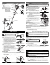
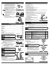
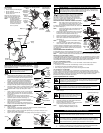
3. Fully press and release the primer bulb 10 times,
slowly. Some amount of fuel should be visible in the
primer bulb and fuel lines (Fig. 11). If you can’t see
fuel in the bulb, press and release the bulb as many
times as it takes before you can see fuel in it.
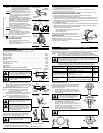
4. With the unit in the starting position, do not squeeze
the throttle control (Fig. 12). Pull the starter rope out
a short distance, until you feel some resistance. This
is usually around 2-4 inches. Then pull the rope
smoothly and briskly. Repeat this 5 times. The
engine should start.
IF
COLD... For cold weather conditions (below 40°F), flip
the Cold Weather Start Lever back up to the
run/open position after the unit has started and
before squeezing the throttle control.
5. Squeeze the throttle control to warm up the engine
for 15 to 30 seconds. In cold weather, let the engine
warm up for 30 to 60 seconds.
IF... The engine does not start, go back to step 3.
IF...
The engine stops while you are squeezing the
throttle, go back to step 4.
STOPPING INSTRUCTIONS
1. Release your hand from the throttle control. Allow
the engine to cool down by idling.
2. Put the On/Off Stop Control in the OFF (O) position.
Fig. 11
Throttle
Control
Fig. 10
Starter
Rope
Fig. 12
Throttle
Control
Start/ On (I)
Stop/ Off (O)
Primer Bulb
Cold Weather
Start Lever
OPERATING INSTRUCTIONS
OPERATING THE RAPID-LINK
™
SYSTEM
The Rapid-Link™ system enables the use of these optional Add-Ons:
Mach IV
®
Trimmer . . . . . . . . . . . . . . . . . . . . . . . . . . . . . . . . . . . . . . . . . . . . . . . . . . . . . . . . . . . . . . . . AF720
Hedge Trimmer . . . . . . . . . . . . . . . . . . . . . . . . . . . . . . . . . . . . . . . . . . . . . . . . . . . . . . . . . . . . . . . . . AH720
Brushcutter . . . . . . . . . . . . . . . . . . . . . . . . . . . . . . . . . . . . . . . . . . . . . . . . . . . . . . . . . . . . . . . . . . . . BC720*
Blower/ Trimmer . . . . . . . . . . . . . . . . . . . . . . . . . . . . . . . . . . . . . . . . . . . . . . . . . . . . . . . . . . . . . . . . . BT720
Blower Vacuum. . . . . . . . . . . . . . . . . . . . . . . . . . . . . . . . . . . . . . . . . . . . . . . . . . . . . . . . . . . . . . . . . . BV720
Cultivator. . . . . . . . . . . . . . . . . . . . . . . . . . . . . . . . . . . . . . . . . . . . . . . . . . . . . . . . . . . . . . . . . . . . . . GC720
Edger. . . . . . . . . . . . . . . . . . . . . . . . . . . . . . . . . . . . . . . . . . . . . . . . . . . . . . . . . . . . . . . . . . . . . . . . . . LE720
Pole Saw . . . . . . . . . . . . . . . . . . . . . . . . . . . . . . . . . . . . . . . . . . . . . . . . . . . . . . . . . . . . . . . . . . . . . . PS720
Straight Shaft Trimmer. . . . . . . . . . . . . . . . . . . . . . . . . . . . . . . . . . . . . . . . . . . . . . . . . . . . . . . . . . . . SS725
Snow Thrower. . . . . . . . . . . . . . . . . . . . . . . . . . . . . . . . . . . . . . . . . . . . . . . . . . . . . . . . . . . . . . . . . . . ST720
Turbo Blower . . . . . . . . . . . . . . . . . . . . . . . . . . . . . . . . . . . . . . . . . . . . . . . . . . . . . . . . . . . . . . . . . . . TB720
*Do NOT use this attachment with an electric powered unit.
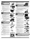
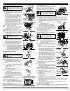
REMOVING THE CUTTING ATTACHMENT OR ADD-ON
1. Turn the knob counterclockwise to loosen (Fig. 13).
2. Press and hold the release button (Fig. 13).
3. While firmly holding the upper shaft housing, pull the cutting
attachment or add-on straight out of the Rapid-Link™
coupler (Fig. 14).
Installing the Cutting Attachment or Add-On
NOTE: Place the unit on the ground or on a work bench to
make add-on installation or removal easier.
1. Turn knob counterclockwise to loosen (Fig. 13).
2. While firmly holding the add-on, push it straight into the
Rapid-Link™ coupler (Fig. 14).
NOTE: Aligning the release button with the guide recess will
help installation (Fig. 13).
3. Turn the knob clockwise to tighten (Fig. 15).
For edging (when using the line head cutting attachment with
Rapid-Link™ models), lock the release button of the cutting
attachment into the 90° edging hole (Fig. 15).
HOLDING THE TRIMMER
Before operating the unit, stand in the operating position (Fig. 16).
Check for the following:
• The operator is wearing eye protection and proper clothing
• With a slightly-bent right arm, the operator’s right hand is holding the shaft grip
• The operator’s left arm is straight, the left hand holding the handle
OPERATING INSTRUCTIONS
WARNING:
Before you begin using any
attachment, read and understand the manual
that came with the attachment. Follow all safety
information contained within.
WARNING:
To avoid serious personal injury
and damage to the unit, shut the unit off before
removing or installing add-ons.
CAUTION:
Lock the release button in the
primary hole and securely tighten the knob
before operating this unit.
CAUTION:
Add-ons are to be used in the
primary hole only. Using the wrong hole could
lead to personal injury or damage to the unit.
WARNING:
Always wear eye, hearing, foot
and body protection to reduce the risk of injury
when operating this unit.
• The unit is at waist level
•
The cutting attachment is parallel to the ground and easily contacts the grass without the need to bend over
Some line breakage will occur from:
• Entanglement with foreign matter
• Normal line fatigue
• Attempting to cut thick, stalky weeds
• Forcing the line into objects such as walls or fence posts
TIPS FOR BEST TRIMMING RESULTS
• For best trimming results, operate unit at full throttle.
• Keep the cutting attachment parallel to the ground.
• Do not force the cutting attachment. Allow the tip of the line to do the cutting, especially along walls.
Cutting with more than the tip will reduce cutting
efficiency and may overload the engine.
• Cut grass over 8 inches (200 mm) by working from top to bottom in small increments to avoid
premature line wear or engine drag.
• Slowly move the trimmer into and out of the cutting area at the desired height. Move either in a
forward-backward or side-to-side motion. Cutting shorter lengths produces the best results.
• Trim only when grass and weeds are dry.
• The life of your cutting line is dependent upon:
• Proper adherence of explained trimming techniques
• What vegetation is cut
• Where vegetation is cut
For example, the line will wear faster when trimming against a
foundation wall as opposed to trimming around a tree.
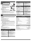
DECORATIVE TRIMMING
Decorative trimming is accomplished by removing all vegetation
around trees, posts, fences and more.
Rotate the whole unit so that the cutting attachment is at a 30°
angle to the ground (Fig. 17).
Guide Recess
Fig. 13
Release
Button
Rapid-Link
™
Coupler
Upper Shaft
Housing
Fig. 14
Lower Shaft
Housing
Primary Hole
Knob
Fig. 15
90˚ Edging Hole
(Trimmer Only)
Fig. 16
Fig. 17
MAINTENANCE AND REPAIR INSTRUCTIONS
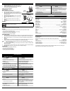
MAINTENANCE SCHEDULE
Perform these required maintenance procedures at the frequency stated in the table. These procedures
should also be a part of any seasonal tune-up.
NOTE: Some maintenance procedures may require special tools or skills. If you are unsure about
these procedures take your unit to any non-road engine repair establishment, individual or
authorized service dealer.
NOTE: Maintenance, replacement, or repair of the emission control devices and system may be
performed by any non-road engine repair establishment, individual or authorized service dealer.
WARNING:
To prevent serious injury, never perform maintenance or repairs with unit
running. Always service and repair a cool unit. Disconnect the spark plug wire to ensure
that the unit cannot start.
FREQUENCY MAINTENANCE REQUIRED SEE
Before starting engine Fill fuel tank with fresh fuel
Check oil
p. 4
p. 6
Every 10 hours Clean and re-oil air filter p. 6
1st change at 10 hours
2nd change at 25 hours
Every 25 hours after
Change oil
Change oil
Clean spark arrestor
p. 6
p. 6
p. 7
10 hours on new engine
Every 25 hours
Every 25 hours
Check rocker arm to valve clearance and adjust
Check rocker arm to valve clearance and adjust
Check spark plug condition and gap
p. 6
p. 6
p. 6
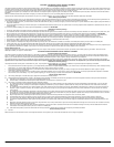
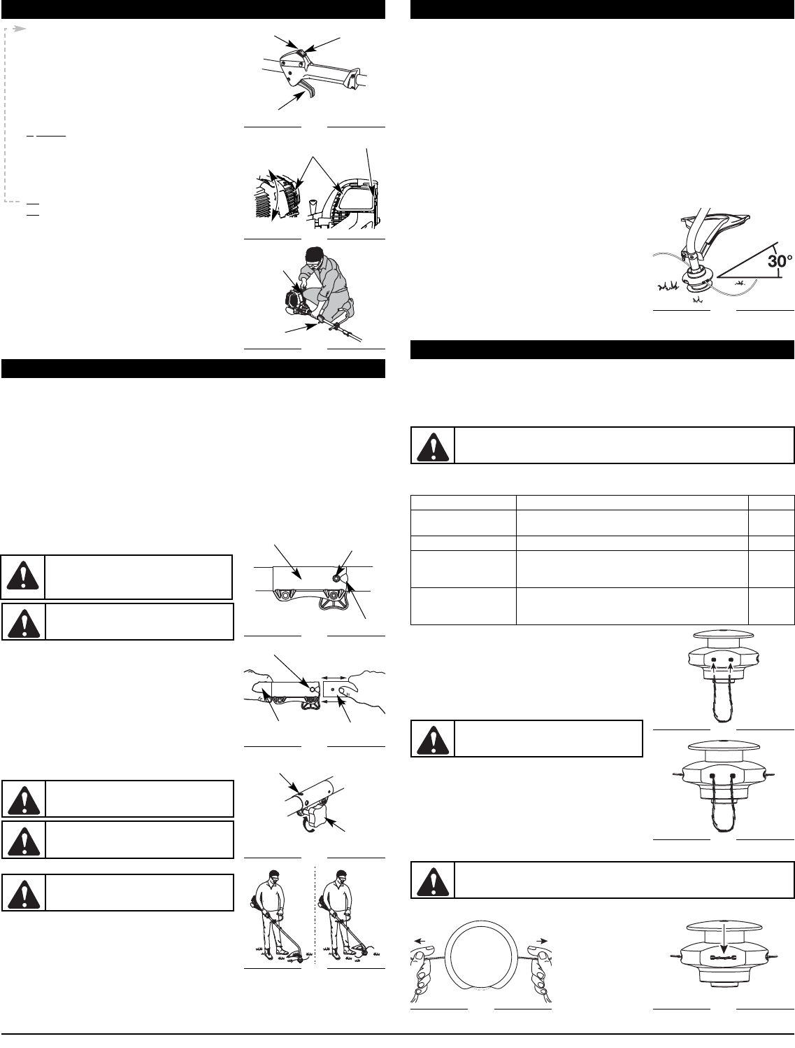
FIXED LINE INSTALLATION
Always use original equipment manufacturer 0.105 inch (2.67 mm)
replacement line. Lines other than those specified may make the
engine overheat or fail.
To install the trimming line:
1. Insert each end of the replacement line into the holes on
either side of retention hook (Fig. 18).
2. Push the ends through until they stick out of the sides of
the head (Fig. 19).
3. Pull the ends through making sure that the ends are of
equal length and the middle of the line is centered between
the insertion holes (Fig. 20).
4. If the ends are not of equal length, push the longer end
back through the head part way and pull the shorter end to
compensate. Repeat until both ends are the same length.
5. Push the trimmer line until it lies flat against the cutting
head (Fig. 21). Make sure the two lengths of cutting line
are of equal length. If they are not, adjust until they are.
WARNING:
Never use metal-reinforced line,
wire, chain, or rope. These can break off and
become dangerous projectiles.
Fig. 18
Fig. 19
Fig. 20
Fig. 21
WARNING:
Always use the correct line length when installing trimming line on the unit.
If the two lengths of cutting line are not of equal length, the unit may develop a vibration.
Run/ Open
Close/ Start