


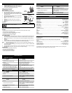
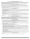
RECOMMENDED OIL TYPE
Using the proper type and weight of oil in the
crankcase is extremely important. Check the oil before
each use and change the oil regularly. Failure to use the correct
oil, or using dirty oil, can cause premature engine wear and
failure. Use a high-quality SAE 30 weight oil of API (American
Petroleum Institute) service class SF, SG, SH.
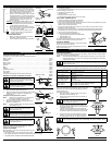
Adding Oil to Crankcase: Initial Use
NOTE: This unit is shipped without oil. In order to avoid
damage to the unit, put oil in the crankcase before
you attempt to start the unit.
Your unit is supplied with one 3.04 fluid oz. (90 ml.) bottle of SAE
30 SF, SG, SH oil (Fig. 6).
NOTE: Save the bottle of oil. It can be used to measure the
correct amount during future oil changes. See
Changing the Oil.
1. Unscrew the top of the bottle of oil and remove the paper
seal covering the opening. Replace the top. Next, cut the
tip off the funnel spout (Fig. 6).
2. Place the unit on a flat level surface (Fig. 7).
3. Remove the oil plug / dipstick from the crankcase (Fig. 8).
4. Pour the entire bottle of oil into the oil fill hole (Fig. 7).
NOTE: Never add oil to the fuel or fuel tank.
5. Wipe up any oil that may have spilled and reinstall the oil
fill plug / dipstick.
Check oil before each use and change as needed. Refer to
Changing the Oil.
RECOMMENDED FUEL TYPE
Old fuel is the primary reason for improper unit performance. Be
sure to use fresh, clean, unleaded gasoline.
NOTE: This is a four cycle engine. In order to avoid damage
to the unit, do not mix oil with gasoline.
Definition of Blended Fuels
Today's fuels are often a blend of gasoline and oxygenates such as ethanol, methanol or MTBE (ether).
Alcohol-blended fuel absorbs water. As little as 1% water in the fuel can make fuel and oil separate or
form acids when stored. Use fresh fuel (less than 60 days old), when using alcohol-blended fuel.
Using Blended Fuels
If you choose to use a blended fuel, or its use is unavoidable, follow recommended precautions:
• Always use fresh unleaded gasoline
• Use the fuel additive STA-BIL® or an equivalent
• Drain tank and run the engine dry before storing unit
Using Fuel Additives
The use of fuel additives, such as STA-BIL® Gas Stabilizer or an equivalent, will inhibit corrosion and
minimize the formation of gum deposits. Using a fuel additive can keep fuel from forming harmful
deposits in the carburetor for up to six (6) months. Add 0.8 oz. (23 ml.) of fuel additive per gallon of fuel
according to the instructions on the container. NEVER add fuel additives directly to the unit's gas tank.
FUELING THE UNIT
1. Remove the fuel cap (Fig. 9).
2. Place the gas container’s spout into the fill hole on the fuel
tank (Fig. 9) and fill the tank.
NOTE: Do not overfill the tank.
3. Wipe up any gasoline that may have spilled.
4. Reinstall the fuel cap.
5. Move the unit at least 30 ft. (9.1 m) from the fueling source and site before starting the engine.
NOTE: Dispose of the old gasoline in accordance to Federal, State and Local regulations.
ASSEMBLY INSTRUCTIONS
OIL AND FUEL INFORMATION
4
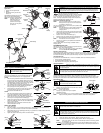
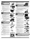
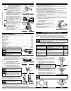
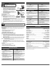
INSTALL CUTTING ATTACHMENT SHIELD
Use the following instructions if the cutting attachment shield on
your unit is not installed. Use only the instructions that apply to
the type of shaft and shield that your unit is equipped with.
CC4125
1. Place the cutting attachment shield onto the shaft housing.
Be sure the guard mounting bracket slides into the slot on
the edge of the cutting shield. Rotate the shield into place,
counterclockwise. The holes in the guard mounting bracket
and cutting attachment shield will line up (Fig. 1).
2. From inside the cutting attachment shield, push the square
bolt through the hole until the threaded end protrudes
through the guard mounting bracket (Fig. 2).
3. Put the washer on the bolt, then screw the wing nut onto
the bolt and tighten. Figure 3 shows the installation
process from underneath the unit.
CC4175
1. Slide the cutting attachment shield into the shield mount
on the cutting attachment. Align the screw holes in the
shield with the holes in the cutting attachment (Fig. 3).
2. Place a hex lock nut into one of the three recessed holes
on the top of the cutting attachment shield (Fig 4).
3. Install a screw into the hole from the bottom of the cutting
attachment shield and screw it into the nut installed in step
2 (Fig. 4). Do not tighten.
4. Repeat steps 2 and 3 until all three screws have been
started, then tighten securely.
ADJUST THE J-HANDLE
1. Loosen the screws.
2. Slide the J-handle in or out until the arrow/white line on the decal touches the clamp assembly
(Fig. 5). You must first loosen the screws if the handle is pre-installed.
3. While holding the unit in the operating position (Fig. 16), position the J-handle to the location that
provides you the best grip.
4. Tighten the clamp screws evenly, until the J-handle is secure.
STARTING AND STOPPING INSTRUCTIONS
STARTING INSTRUCTIONS
1. Check the oil level in the crankcase. Refer to Checking the Oil Level.
2. Fill the fuel tank with fresh, clean unleaded gasoline. Refer to Fueling the Unit.
NOTE: There is no need to turn the unit on. The On/Off Stop Control is in the ON (I) position
at all times (Fig. 10).
IF
COLD... For cold weather conditions (below 40°F), flip the Cold Weather Start Lever (Fig. 11)
down to the start/closed position and continue to step 3. DO NOT flip this lever down if
the temperature is above 40°F.
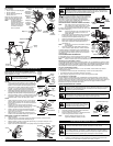
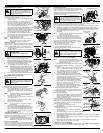
KNOW YOUR UNIT
Applications:
• Cutting grass and light weeds.
• Edging
• Decorative trimming around trees,
fences, etc.
Other optional accessories may be used
with your unit. Refer to Operating the
Rapid-Line™ System for a list of add-ons.
NOTE: The below illustration may
differ slightly from your
unit. For example, the
picture shows a straight
shaft. Your unit may have a
curved shaft.
CC4125
Primer
Bulb
Oil Fill Plug
Spark Plug
Air Filter Cover
Cutting Attachment
Shield
Fuel Cap
Throttle
Control
J-Handle
Cutting Attachment
Shaft Grip
On/Off Stop
Control
Shaft Housing
Starter Rope
Grip
Line Cutting
Blade
Muffler
Spark Arrestor
Muffler Guard
Rapid-Link™
CC4175
KNOW YOUR UNIT
Screws (4)
J-Handle
Fig. 5
Decal
Shaft Housing
Shield Mount
Cutting
Attachment
Shield
Cutting Attachment
Fig. 3
Nuts (3)
Recessed Holes
Hex Lock
Nut
Screws (3)
Fig. 4
Cutting
Attachment
Shield
Fig. 1
Washer
Fig. 2
WARNING:
To prevent serious personal injury,
never operate the trimmer without the cutting
attachment shield in place.
WARNING:
OVERFILLING THE CRANKCASE WITH OIL MAY CAUSE SERIOUS PERSONAL
INJURY. Check and maintain the proper oil level in the crank case; it is important and cannot be
overemphasized. Check the oil before each use and change it as needed. See Changing the Oil.
WARNING:
Add fuel in a clean, well ventilated outdoor area. Wipe up any spilled fuel
immediately. Avoid creating a source of ignition for spilt fuel. Do not start the engine until
fuel vapors dissipate.
WARNING:
Gasoline is extremely flammable. Ignited vapors may explode. Always stop
the engine and allow it to cool before filling the fuel tank. Do not smoke while filling the
tank. Keep sparks and open flames at a distance from the area.
WARNING:
Remove fuel cap slowly to avoid
injury from fuel spray. Never operate the unit
without the fuel cap securely in place.
Shaft
Housing
Guard
Mounting
Bracket
Fig. 7
Funnel
Spout
Fig. 6
Oil Fill Plug
Fig. 8
O-Ring
Oil Fill Hole
Gas Can Spout
Fig. 9
Fuel Cap
Fuel Tank
WARNING:
Operate this unit only in a well-ventilated outdoor area. Carbon monoxide
exhaust fumes can be lethal in a confined area.
WARNING:
Avoid accidental starting. Make sure you are in the starting position when
pulling the starter rope (Fig. 13). To avoid serious injury, the operator and unit must be
in a stable position while starting. Make sure that any Add-On item is installed correctly
and secure before starting the unit.
Top
Clamp
Bottom
Clamp
Middle
Clamp
Wing Nut
Guard Mounting
Bracket
Square
Bolt
Fill Level