


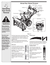

14
5
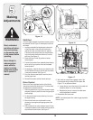
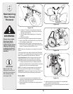
Making
Adjustments
WARNING
Read, understand,
and follow all instruc-
tions and warnings
on the machine and
in this manual before
operating.
Never attempt to
make any adjust-
ments while the
engine is running,
except where speci-
fied in operator’s
manual.
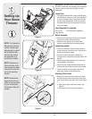
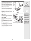
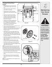
Shift Rod
If the full range of speeds (forward and reverse) cannot
be achieved, refer to Figure 15 and adjust the shift rod
as follows:
1. Looking underneath the handle panel, note which
of the three holes in the shift lever the ferrule is
inserted into. Also note the direction of insertion.
Then remove the internal cotter pin and flat washer
from the ferrule and withdraw the ferrule from the
shift lever. See Figure 15.
2. Place shift lever in sixth (6) position or fastest
forward speed.
3. Push shift rod and shift arm assembly down sharply,
as far as it will go to put the drive into the fastest
forward position.
4. As necessary, rotate the ferrule up or down the shift
rod until the ferrule lines up with the hole from which
it was earlier removed. See Figure 15.
5. From the direction noted earlier, insert the ferrule
into the proper hole.
6. Reinstall the washer and the internal cotter pin.
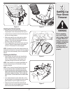
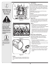
Drive Control
Refer to the Final Adjustment section of the Set-Up
instructions to adjust the drive control. To further check
the adjustment, proceed as follows:
1. Drain the gasoline out of your snow thrower’s engine,
and place a piece of plastic film under the gas cap to
avoid spillage.
2. Tip the snow thrower forward, allowing it to rest on
the auger housing.
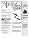
3. Remove the frame cover underneath the snow
thrower by removing the self-tapping screws. See
Figure 16.
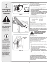
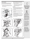
4. With the wheel drive control released, check if there
is clearance between friction wheel and drive plate in
all positions of the shift lever. See Figure 17.
5. With the drive control lever engaged, check if the
friction wheel solidly contacts the drive plate. See
Figure 17. If not, adjust as follows:
a. Loosen the jam nut on the traction drive cable and
thread the cable in or out as necessary.
b. Retighten the jam nut to secure the cable when
correct adjustment is reached.
6. Reassemble the frame cover.
NOTE: If you placed plastic film under the gas cap earlier,
remove it now.
Figure 15
Figure 16
Figure 17
Axle Supp.
Brkt.
Opening
Drive
Plate
Friction
Wheel