


20
level, paved area. If the leaking tire is on a
traction wheel, put blocks on each side of the
opposite traction wheel and jack up the tire
that leaks about an inch off the ground.
Loosen and remove the lug nuts and remove
the wheel. Mount a wheel and tire, replace the
lug nuts, and using a torque wrench, tighten
them to 60
±
10 ft-lbs.
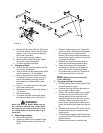
If the leaking tire is on a front caster wheel,
block both traction wheels and raise the
caster wheel so that the tire is an inch off the
ground. Loosen and remove the locknut from
the axle assembly and pull the axle assembly
from the caster yoke. The wheel and two
spacer sleeves will drop free. Slip the axle
assembly through one side of the caster
yoke, through a spacer sleeve, a wheel, the
other spacer sleeve and finally through the
other side of the caster yoke. Then tighten
the locknut on the end of the axle assembly.
Lower the mower off the jack and continue
mowing. The wheel with the leaking tire
should be inflated to 20 psi and the wheel
placed in a large bucket of water. Carefully
inspect the tire, rim and valve for escaping air
bubbles which indicate a leak. Mark each
leak with a yellow marking crayon and then
deflate the tire to 8 psi and repeat the
inspection. If the leaks you find are pin hole
size to 1/16" diameter, the tire can be
repaired. If the leaks are larger than 1/16"
diameter, the tire can be repaired. If the tire
bead is damaged, the tire can be repaired or
the tire will have to be replaced.
3.
Creeping:
Creeping is the slight forward or
backward movement of the mower when the
throttle is on and the lapbars are in the
opened-out position. If your mower creeps do
the following.
a. Jack up rear of unit.
b. Place Lapbars in neutral opened-out posi-
tion.
c. Locate jam nuts on transaxle control arms.
(They are on the vertical linkage on the
front of the transaxles)
d. Loosen jam nuts on both ends of rod con-
nectors.
e. Start unit and push throttle all the way on.
f. If unit creeps forward, rotate vertical rod
links counter-clockwise. If unit creeps in
reverse, rotate clockwise.
Adjust the appropriate rod connector. The
left rod for the left side of the mower and
the right rod for the right side of mower.
Afterward, retighten jam nuts.
E. Brakes
While the mower is in motion, all braking is performed
dynamically through the hydraulic pumps and traction
motors, controlled by the two steering levers. When the
mower is parked with the engine shut off, the hydraulic
system locks the traction wheels.
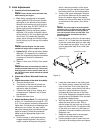
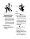
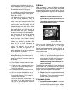
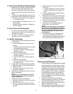
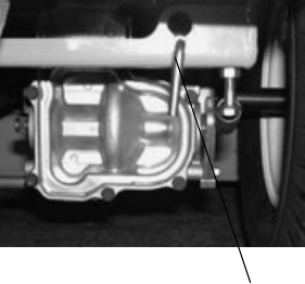
Note:
To move the mower forward or in
reverse by pushing, you must release the
dynamic braking. Locate the release levers at
the rear of the machine. Pull them toward the
rear and lower the wide area of the rod into the
keyhole slot. (See photo below)
.
When the mower is parked with the engine running
and the steering levers opened out in the neutral
position, the parking brakes should be applied. The
parking brakes are gear/pawl brakes mounted on
each traction wheel. They are both engaged by the
same operating lever.
1.
Adjustments:
The parking brake handle is a
lever in a “j” slot that should engage with mod-
erate force. The parking brakes provide a
positive means to hold a machine stationary
that is similar to “Park” on an automobile.
Note:
The parking brakes normally do not
need to be adjusted.
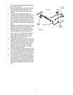
To adjust either brake individually, loosen the jam nuts
on the cable near the brake arm on the transaxle.
Adjust the nuts so that the brake/pawl comes closer to
the gear, but not in contact with the gear teeth.
2.
Repair:
The mower is equipped with external
gear/pawl brakes and will not normally require
maintenance. If they are not working properly,
please contact your service center.
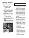
F. Hydraulic System
1.
Hydrostatic Pumps and Motors:
The pumps
in the transaxles are the hardest-working
components in the hydraulic system. They are
in operation all the time the engine is running.
Hydro Release Valve