


18
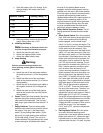
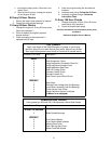
c. Store the battery with a full charge. A dis-
charged battery will freeze (refer to the
table below).
d. Recharge battery when ever the specific
gravity value is less than 1.225
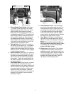
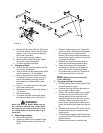
4. Installing the Battery
Note:
The battery is delivered from the fac-
tory fully charged and filled with electrolyte.
a. Attach the positive (red) cable.
b. Attach the negative (black) cable.
c. Attach the rubber battery strap.
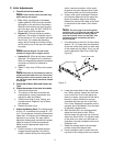
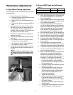
5. Jump Starting
Warning:
Failure to use this starting procedure can
cause sparking, and the gases in the battery
to explode.
a. Attach the end of the red jumper cable to
the positive terminal (+) of the charged bat-
tery.
b. Attach the other end of the red jumper
cable to the positive terminal (+) of the low
charge battery.
c. Attach the end of the black jumper cable to
the negative terminal of the charged bat-
tery.
d. Attach the other end of the black jumper
cable to the frame of the unit with the low
charge battery.
6.
Fuses:
There is one fuse located in the wiring
between the ignition and start switch and
other electrical components. This is a stan-
dard plug-in type automotive fuse rated at 7.5
amp.
7.
Safety Switches:
There are seven safety
switches in the electrical circuit which control
the engine. They are (1) the blade clutch
switch, (2) the parking brake switch, (3) the
left and (4) the right steering lever switches,
(5) the seat switch, (6 and 7) the no cut in
reverse switches.They operate so that in order
to start the engine, the blade clutch switch
must be off, the parking brake must be
engaged, and both steering levers must be
opened-out to the side in the neutral position.
Once the engine is started, the seat must be
occupied and the parking brake must be
released before either of the steering levers is
folded up to the operating position or the
engine’s electronic ignition will be grounded
out and the engine will stop. Also, the seat
must be occupied before the blade clutch
switch can cause the blades to rotate.
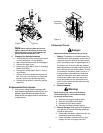
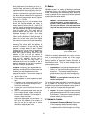
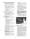
8.
Safety Switch Operation Checks:
The fol-
lowing operational checks should be made
daily.
a.
Blade Clutch Switch:
Sit in the operator’s
seat. With both steering levers opened-out
in the neutral position and the parking
brake engaged, turn the blade clutch
switch “on” and try to start the engine. The
engine should not start. If it does, the blade
clutch switch must be replaced. If the
engine does not start, turn the blade clutch
switch “off” and start the engine. Now turn
the blade clutch switch “on” and the blades
should rotate. If the blades do not turn, the
blade clutch switch must be replaced, the
seat switch must be replaced or the elec-
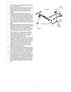
tric PTO clutch must be repaired. The air-
gap should be checked every 200 hrs. (or
less, if severe operating conditions exist
such as when there are many on/off
cycles, mulching operations, material col-
lection systems used, and dusty/dirty con-
ditions), and the air-gap adjusted if more
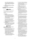
than 0.035". To inspect, remove the “nega-
tive” cable from the battery and all spark-
plug wires. The air-gap should be checked
with feeler gages in the three slots of the
BBC. The air-gap should be adjusted to
0.013" to 0.015". There are three inspec-
tion slots I the brake cover. To adjust, suc-
cessively tighten each of the three gap
adjustment nuts an equal amount. Insert a
feeler gage (0.013" to 0.015") into each
slot as the air gap adjustment nut are tight-
ened. The correct adjustment occurs when
slight contact with the feeler gage occurs.
Engage the BBC a couple of times, and re-
check the air-gap. If it is not between
0.013" and 0.015", repeat the adjustment
procedure.
b.
Parking Brake Switch:
Sit in the opera-
tor’s seat. With both steering levers
opened-out in the neutral position and the
blade clutch switch “off”, release the park-
ing brake and try to start the engine. The
engine should not start. If it does, the park-
Specific Gravity Freezing Temp (°F)
1.265 -71
1.250 -62
1.200 -16
1.150 5
1.100 16