


40
B. DECK LEVELING ADJUSTMENTS
The 48" mower deck is equipped with ground following
front castor wheels and is designed to run on its own
wheels. However, to ensure even cutting, the mower
deck should be properly leveled. The leveling
procedure will result in the left and right blades having
corresponding cutting-edge-to ground measurements
within 1/16 inch of each other. Also, the blades will
have a downward tilt toward the front of the tractor of
approximately 1/8 to 1/4 inch. To level the mower deck,
proceed as follows:
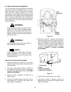
WARNING
Before making any adjustments, place the PTO
switch in the “OFF” position, engage the brake
pedal lock, turn the ignition key to the “OFF”
position, remove the key from the switch and
remove the spark plug wire to avoid accidental
starting and injury.
WARNING
When adjusting the mower deck, be careful not
to cut yourself on the sharp blades.
NOTE
Check for proper tire inflation before making a
leveling adjustment. The tractor and deck
MUST be placed on a hard, level surface during
leveling adjustment.
SIDE TO SIDE LEVELING ADJUSTMENT
1. Position the tractor and mower on a hard, level
surface. Open the tractor hood and disconnect the
spark plug wires.
2. The mower deck wheels should be installed in
their uppermost position to prevent contact with
the hard, level surface below. Refer to CUTTING
HEIGHT ADJUSTMENT.
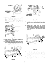
3. Raise the tractor implement lift handle to its
highest setting.
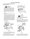
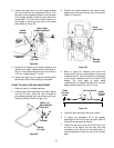
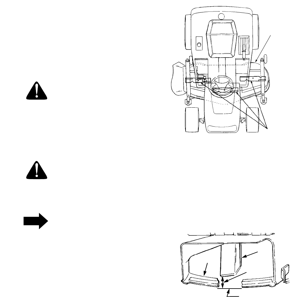
4. Position the mower blades so that the ends of
each blade face the right and left sides of the
tractor (Refer to Figure 56).
Figure 56
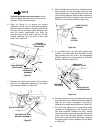
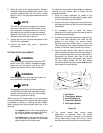
5. Referring to Figure 57, measure and record the
distance from the hard, level surface to the outer-
most cutting edge of the right blade. Repeat this
step for the left blade. If the two blade heights are
not within 1/16 inch, proceed to steps 6, 7 and 8.
If the two blade heights are within 1/16 inch,
proceed to FRONT TO BACK LEVELING
ADJUSTMENT.
Figure 57
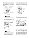
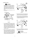
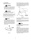
6. Lower the deck onto the hard, level surface.
7. Side-to-side leveling is obtained utilizing the
adjustment ferrule and right hand hanger bracket
(Refer to Figure 58).
MOWER
BLADES
DECK
INSTALLED
1.
Finger guard
2. Blade
3. Hard Level Surface
4. Measure This Distance
1
2
3
4