


10
4.
Electric Blade Clutch Switch:
(See Figure
1.) Located on the right side of the mower
beside the ignition switch. This is an “on/off”
push pull switch that controls the electric
blade clutch which supplies power to the cut-
ting blades through the PTO. The switch must
be cut off to start the engine and should be off
for safety any time another person
approaches the mower or the mowing deck is
raised to the transport position. Power to the
electric clutch will also be cut off if the opera-
tor leaves the operator’s seat.
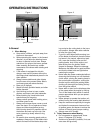
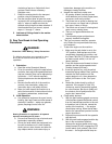
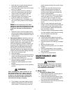
5.
Parking Brake:
(See Figure 3.) Located on
the left side of the traction unit. The handle is
an overcenter lever which applies the internal
drum-type brake on each drive wheel when
the handle is in the up position. The brake
must be engaged in order to start the engine.
6.
Deck Lift Handle and Optional Foot Pedal
Lift Assist:
(See Figure 3.) Located on the
right front corner of the mowing deck. Raise
the mowing deck to the transport position, by
pulling the lever to the rear and moving it
inward into the stop for transport. To lower the
mowing deck, pull the deck lift handle and
move it outward. This lower’s the deck to the
cutting position.The foot pedal lift assist (not
pictured above) can provide “lift assist” to the
hand lever or with “foot effort only”. To provide
assistance to the lift handle: remove the hair-
pin clip from the locking pin and remove the
pin from the pedal assembly. Fold the pedal
down to the horizontal position so the hole in
the pedal aligns with the hole in the lever. Re-
install the locking pin and hairpin clip. Pull on
the Lift handle and depress the foot pedal to
raise the deck. Lifting with “foot effort only”
depress the foot pedal (the hand lever will lock
into transport position if fully depressed). To
release the lift mechanism depress the foot
pedal, move the hand lever outward and
slowly reduce foot pedal effort to lower the
mechanism. To service the unit: Remove the
hairpin clip from the locking pin and remove
the pin from the pedal assembly. Fold the
pedal up to vertical position so the hole in the
pedal aligns with the hole in the lever. Rein-
stall the locking pin and hairpin clip. This is
the required position for the foot pedal for the
foot platform to tilt forward and to access
some of the machines components.
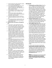
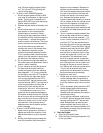
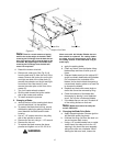
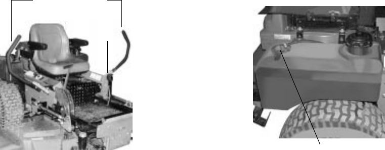
7.
Fuel Shutoff Valve:
(See Figure 4.) Located
on top of the fuel tank(s). When turned in a
clockwise direction until it stops, it will shut off
the flow of fuel to the engine. When turned in
a counterclockwise direction it will open and
allow fuel to flow to the engine. Close this
valve anytime the mower is trailered or you
are not going to run the mower for a period of
30 minutes or more to prevent flooding the
engine.
8.
Seat Adjustment Lever:
The Seat Adjust-
ment Lever is located beneath the seat. The
Seat Adjustment Lever is used to move the
seat forward and backward. To place the seat
in the desired position pull the seat adjust-
ment lever to the left then push the seat for-
ward or back to the desired position. Release
the lever so the seat will lock in place.
9.
Digital Tachometer and Hour Meter:
(See
Figure 1) Located on the right side of the
mower in front of the ignition switch. When the
machine is running the tachometer displays
engine rpm. When the machine is off the
tachometer displays running time.
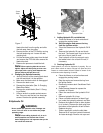
10.
Choke Lever:
(See Figure 2) The Choke
Lever is located on the left instrument panel
next to the seat. The Choke Lever is operated
manually. Having the Choke Lever in the ON
position helps the engine to start during initial
start-up. During normal operation the Choke
Lever should be in the OFF position.
Note:
There will be a flashing “LUBE” for
each recommended lubrication interval. There
Brake
Steering Levers
Deck Lift Handle
Figure. 3
Fuel Shutoff Valve
Figure. 4