


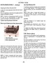

ELECTRIC LIFT
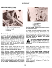
OPERATING INSTRUCTIONS
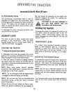
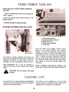
1. Locking knob2.
Cam stop3.
Rockshaft arm
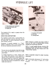
1. Float lockout pin (optional)2.
Electric lift unit
3. Pivot pin
described on page 15 to allow implement to return
to a single preset hei~ht.
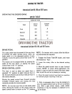
To operate equipment in a fixed "locked" posi-
tion, where down pressure of implement is re-
quired (that is blade work); remove frame cover
and remove cotter pin in pivot. Reverse lock pin
(optional) and insert into pre-aligned holes in clevis
and lower portion of rockshaft arm. Replace
washer and cotter pin.
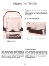
The electric lift is operated by a control switch on
the upper right-hand corner of the instrument
panel. To raise the implement push upward on
control switch until desired height is reached, then
release the switch. Switch will return to the center
or neutral position. Equipment will stay in a given
position when you release the switch. To lower
equipment push down on the control switch.
Switch will again return to the central or neutral
position when you release it.
A CAUTION! Always stop the engine and
set the brake pedal in the locked posi-
tion before making any adjustments to
the machine.
NOTE: Remove or position cam stop on side of
frame for full travel of rockshaft before locking
rockshaft arms as described above.
NOTE: Always operate electric lift with tractor
engine running. Operation of electric lift off the
battery will cause premature battery failure.
NOTE: To avoid possible damage, as soon as the
operation requiring "Down Pressure" is completed,
immediately return the float lockout pin to the
"Free to Float" position.
NOTE: Whenever raising or lowering equipment
release control switch when equipment has reached
a fully raised or lower position. Holding control
switch will cause protective switch to open the
circuit. Lift will function after waiting 30 seconds.
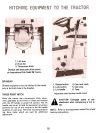
Refer to equipment manual for proper mounting
instructions.
Equipment is normally operated in a "Float"
position (implement free to move upward) with
lock pin (optional) positioned as shown. Cam stop
on the outside of the frame may be adjusted as
NOTE: Periodically lubricate pin "A" with a few
drops of engine oil.
19