


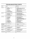

ERVNCE AND ADJUSTMENTS
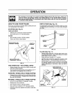
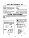
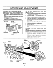
TO REMOVE BELT GUARD (See Fig, 24)
NOTE: Forease ofremoval,removehairpinclipandclevis
pinfrom leftwheel. Pullwheel outfrom tillerabout 1 inch°
• Remove two(2) capnutsandwashersfrom sideofbelt
guard°
• Remove hex nut andwasher from bottom of belt guard
(located behind wheel).
° Pull belt guard out and away from unit,
° Replace belt guard by reversing above procedure°
BELT GUARD CAP NUT
AND WASHER
HE]< NUT
AND
WASHER
(LOCATED
BEHIND
TIRE)
CAP NUT
AND WASHER
HAIRPIN CLIP AND
CLEVIS PiN
FIG. 24
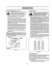
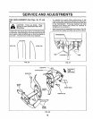
TO REPLACE GROUND DRIVE BELT (See
Figs. 24 and 25)
, Moveleft wheel and remove belt guard as described in
"TO REMOVE BELT GUARD",
• Loosen belt guides "A" and "B"and also nuts "C" and
• Remove old belt by slipping from engine pulley first,
• Place new belt in groove of transmission pulley and
into engine pulley_ BELT MUST BE IN GROOVE ON
TOP OF IDLER PULLEY° NOTE POSITION OF BELT
TO GUIDES,
• Tighten belt guides "A" and "B" and nuts "C" and "D".
° Check belt adjustment as described below,
. Replace belt guard°
• Reposition wheel and replace clevis pin and hairpin
clip.
GROUND DRIVE BELT ADJUSTMENT (See
Fig. 25)
For proper belt tension,the extensionspring should have
about 5/8 inch stretch when drive control bar is in "EN-
GAGED" position, Thistension can be attained asfollows:
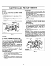
• Loosen cable clip screw securing the drive control
cable_
• Slide cable forwardfor less tension and rearward for
more tension until about 5/8 inch stretch is obtained
while the drive control bar is engaged°
• Tighten cableclip screw securely,
NUT "C"
ENGINE
PULLEY
BELT
BELT
GUIDE "B"
\
CABLEC_P
DRIVE
CONTROL
CABLE
LESS
TENSION
NUT "D"
IDLER
PULLEY
TRANSMISSION
PULLEY
SPRING
FIG. 25
17