


iiiii1,,11,,1111,11,,11,1,,,,11,1,,,i iiii ,, ii ..............................
SERVSCE AN ADJUSTMENTS
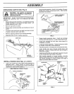
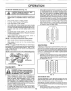
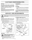
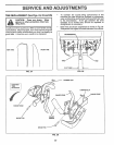
TO REMOVE BELT GUARD (See Fig. 22)
, Remove LH, inner and outer side shields (See "TO
REMOVE WHEEL" in this section of this manual),
, Remove hair pin clip and clevis pin from left wheel Pull
wheel out from tiller' about I inch..
• Remove two (2) cap nuts and washers from side of belt
guard
• Remove hex nut and washer from bottom of belt guard
(located behind whee!)_
, Pull belt guard out and away from unite
" Repface belt guard by reversing above procedure..
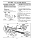
BELT GUARD CAPNUT
AND WASHER
HEX NUT
AND
WASHER
(LOCATED
BEHIND
TIRE)
CAP NUT _ "
AND WASHER ' HAIRPIN CLIP AND
CLEVIS PIN
FIG, 22
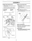
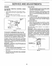
TO REPLACE GROUND DRIVE BELT (See
Figs. 22 and 23)
o Remove belt guard_ (See''TO REMOVE BELTGUARD"
in this section of this manual)_
Loosen belt guides "A" and "B" and also nuts "C" and
°
o
u
Remove old belt by slipping from engine pulley first..
Place new belt in groove of transmission pulley and
intoengine pulley BELT MUST BE IN GROOVE ON
TOP OF IDLER PULLEY NOTE POSITION OF BELT
TO GUIDES.
= Tighten belt guides "A" and "B" and nuts "C" and "D".
- Check belt adjustment as described below.
= Replace belt guard.
= Reposition wheeI and replace clevis pin and hairpin
clip.
° Replace inner and outer side shields..
GROUND DRIVE BELT ADJUSTMENT (See
Fig. 23)
For proper belt tension, the extension spring should have
about 5/8 inch stretch when drive control bar is in "EN-
GAGED" position..This tension can be attained as follows:
• Loosen cable clip screw securing the drive control
cable..
o Slide cable forward for less tension and rearward for
more tension until about 5/8 inch stretch is obtained
while the drive control bar is engaged,,
° Tighten cable clip screw securely..
ENGINE
PULLEY
BELT
CABLE CLtP
SCREW
BELT IVE
GUIDE"B" CONTROL
CABLE
LESS
TENSION
NUT "D"
IDLER
PULLEY
TRANSMISSION
PULLEY
EXTENSION
SPRING
FIG. 23
16