


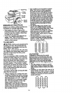
NOTE:Whenreassemblingoutertines,
besurerighttine assembly(marked"R")
and left tine asseml:tly (marked =L") are
mounted to correctslde of tine shaft.
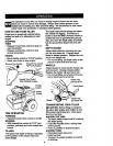
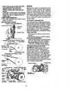
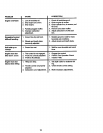
TINE OPERATION CHECK
WARNING: Disconnect spark plug wire
from spark plug to preventstarting while
checking tine operation.
For proper tine operation, forward tine con-
trol lever must be against controlbody and
all slack removedfrom inner wire of control
cable when controlis inthe "OFP (up)
position.
If lever and cable are loose, loosen cable
clip at lower end ofcable. Pull up on cable
to remove slack without extendingspring
on end of cable, and retighten cable c p.
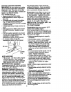
FINAL CHECK "OFF" POSITION
• With tine control =OFP (up), push down
on handle to raise tines off the ground.
• Slowly pull recoil starter handle while
observing tines. Tines should not
rotate.
• If tines rotate, inner wire of control cable
is too tight which is extending lower
spring and engaging tines. Loosen
cable clip and push down on cable only
enough to relieve spring tension.
Tighten cable clip.
• Recheck in =OFP position and adjust if
necessary.
FINAL CHECK "ON" POSITION
• With tine control =ON" (held down to
handle) push down on handle to raise
tines off the ground.
• Slowly pull recoil Starter handle while
observing tines. Tines should rotate for-
ward.
• If tines do not rotate), inner wire of con-
trol cable is too loose. Loosen cable clip
and pull cable up to remove slack and
retighten clip.
• Recheck in "ON" position and adjust if
necessary.
NOTE: If =ON" position check required
adjustment, recheck =OFP position adjust-
ment to insure tines do not rotate when
control is "OFP (up).
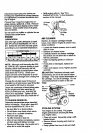
line Control "OFP Positiion
=ody
_ne Control
"ON" Position
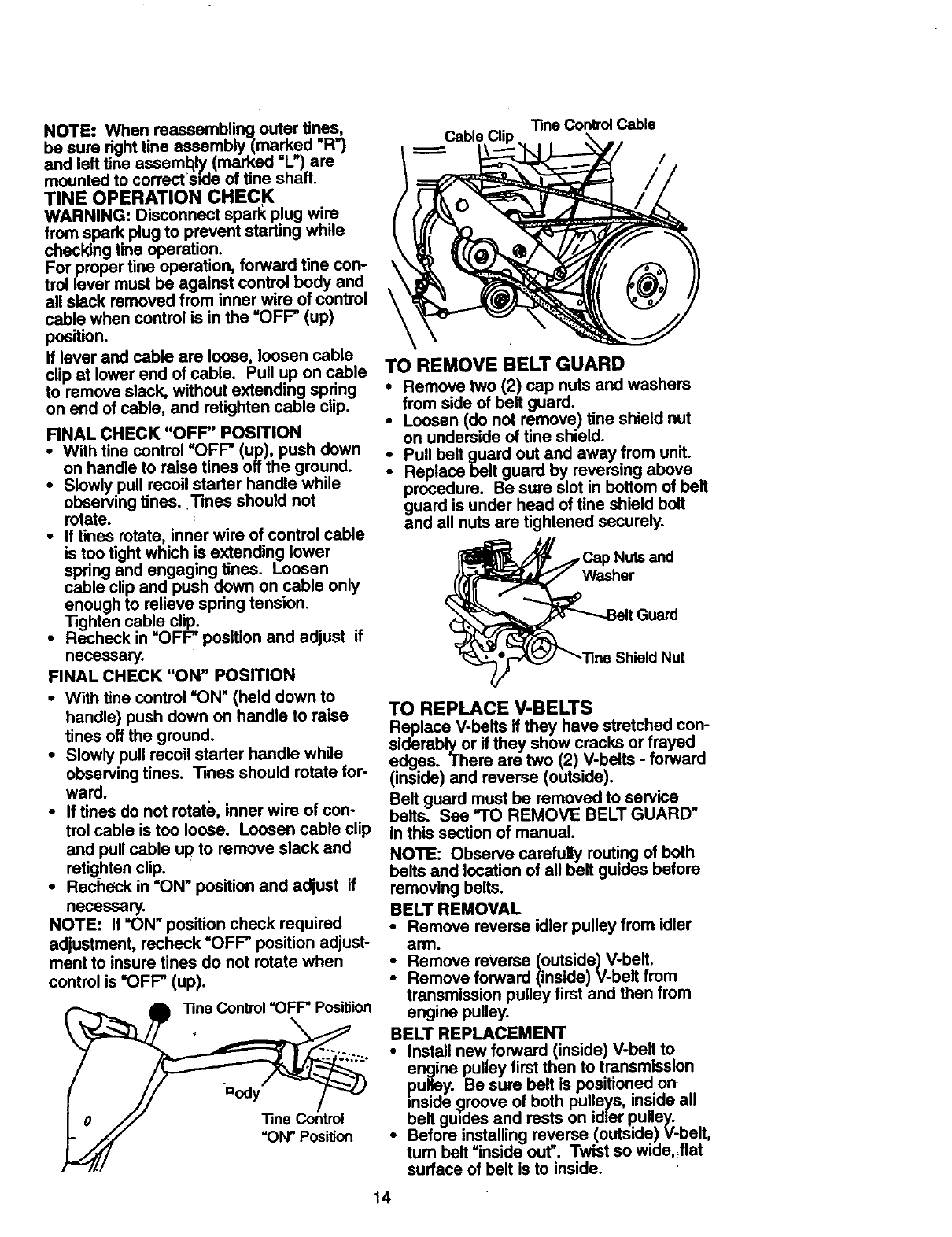
"fine Control Cable
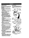
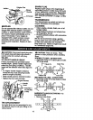
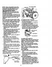
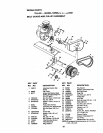
TO REMOVE BELT GUARD
• Remove two (2) cap nuts and washers
from side of belt guard.
• Loosen (do not remove) tine shield nut
on underside of tine shield.
Pull belt guard out and away from unit.
•" Replace belt guard by reversing above
procedure. Be sure slot in bottom of belt
guard is under head of tine shield bolt
and all nuts are tightened securely.
_Nuts and
Washer
_hieldNut
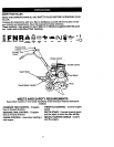
TO REPLACE V-BELTS
Replace V-belts if they have stretched con-
siderably or if they show cracks or frayed
edges. There are two (2) V-belts - forward
(inside) and reverse (outside).
Belt guard must be removed to service
belts. See "TO REMOVE BELT GUARD"
in this section of manual.
NOTE: Observe carefully routing of both
belts and location of all belt guides before
removing belts.
BELT REMOVAL
• Remove reverse idler pulley from idler
arnl.
• Remove reverse (outside) V-belt.
Remove forward (inside) V-belt from
transmission pulley first and then from
engine pulley.
BELT REPLACEMENT
• Install new forward (inside) V-belt to
engine pulley first then to transmission
pulley. Be sure belt is positioned on
inside 9roove of both pulleys, inside all
belt guides and rests on idler pulley.
• Before installing reverse (outside) V-belt,
turn belt =inside out". Twist so wide, flat
surface of belt is to inside.
14