


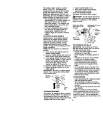
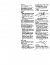
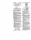
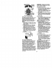
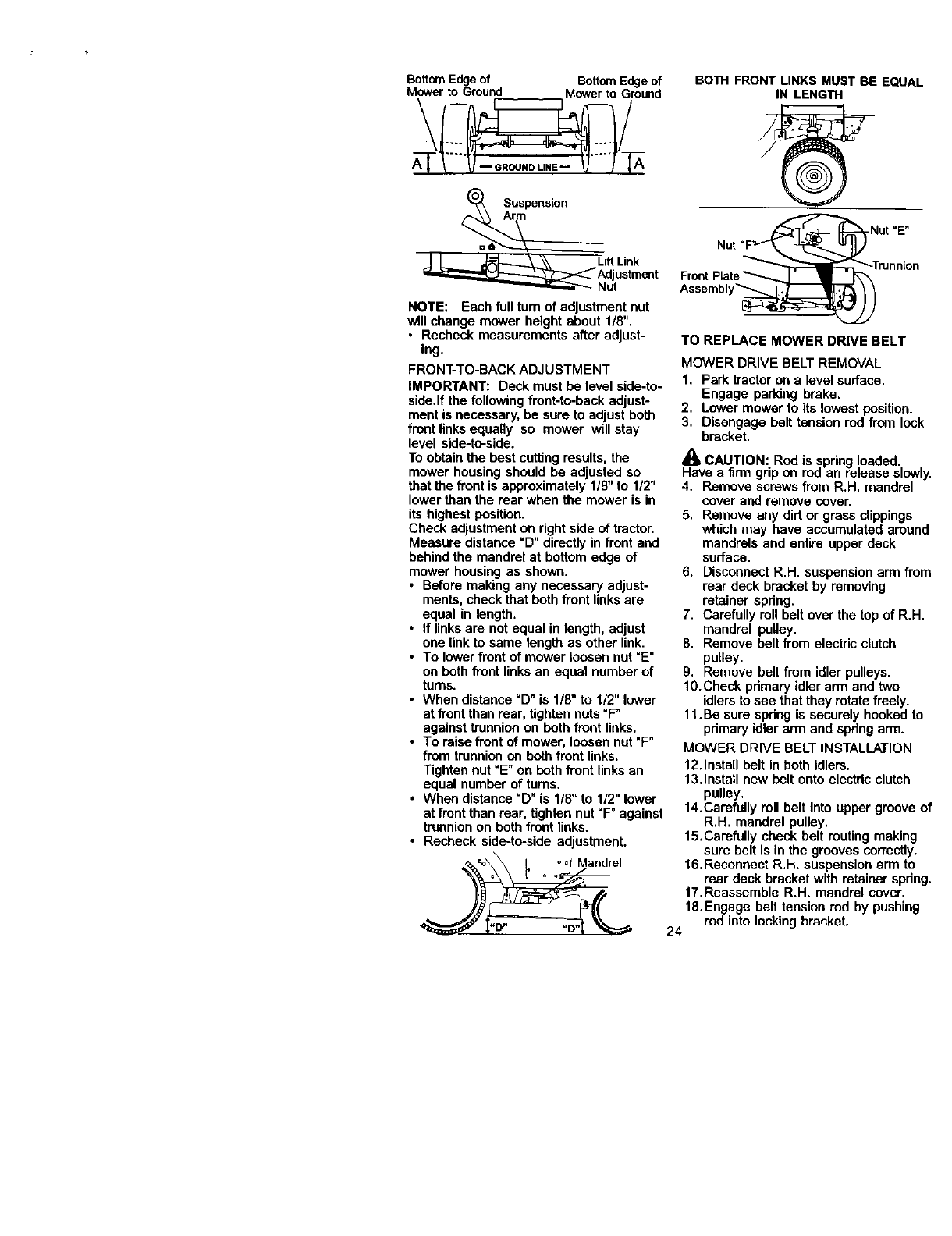
BottomEdgeof BottomEdgeof
MowertoGround MowertoGround
\ /
A_SUspensi°n
LiftLink
Adjustment
Nut
NOTE: Each full turn of adjustment nut
will change mower height about 1/8".
• Recheck measurements after adjust-
ing.
FRONT-TO-BACK ADJUSTMENT
IMPORTANT: Deck must be level side-to-
side.If the following front-to-back adjust-
ment isnecessary, be sure to adjust both
front linksequally so mower willstay
level side-to-side.
To obtain the best cutting results,the
mower housing should be adjusted so
that the front is approximately 1/8" to 1/2"
lower than the rear when the mower is in
its highest position.
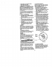
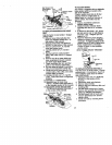
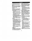
Check adjustment on right side of tractor.
Measure distance =D" directly in front and
behind the mandrel at bottom edge of
mower housing as shown.
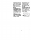
• Before making any necessary adjust-
ments, check thatboth front linksare
equal in length.
• If links are not equal in length, adjust
one linkto same length as other link.
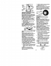
• To lower front of mower loosen nut "E"
on both front links an equal number of
turns.
• When distance =D" is 1/8" to 1/2" lower
at front than rear, tighten nuts=F"
against trunnionon beth front links.
• To raise front of mower, loosen nut"F"
from trunnion on both front links.
Tighten nut "E" on beth front linksan
equal number of turns.
• When distance "D"is 1/8" to 1/2" lower
at front than rear, tighten nut"F" against
trunnion on bothfront links.
• Recheck side-to-side adjustment.
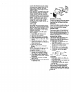
BOTH FRONT LINKS MUST BE EQUAL
IN LENGTH
Nut "E"
Assembly_
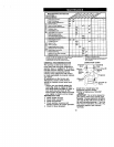
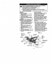
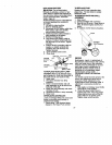
TO REPLACE MOWER DRIVE BELT
MOWER DRIVE BELT REMOVAL
1. Park tractor on a level surface.
Engage parking brake.
2. Lower mower to its lowest position.
3. Disengage belt tension rod from lock
bracket.
K_aCAUTION: Rod is springloaded.
vea nrm grip on roa an release slowly.
4. Remove screws from R,H. mandrel
cover and remove cover.
5. Remove any dirt or grass clippings
which may have accumulated around
mandrels and entire upper deck
surface.
6. Disconnect R.H. suspension arm from
rear deck bracket by removing
retainer spring.
7. Carefully roll belt over the top of R.H.
mandrel pulley.
8. Remove belt from electricclutch
pulley.
9. Remove belt from idler pulleys.
10.Check primary idler arm and two
idlers to see that they rotate freely.
11.Be sure spdng is securely hooked to
primary idler arm and spdng arm.
MOWER DRIVE BELT INSTALLATION
12. Install belt in both idlers.
13.Install new belt onto electdc clutch
pulley.
14.Carefully roll belt into upper groove of
R.H. mandrel pulley.
15. Carefully check belt routingmaking
sure belt is in the grooves correctly.
16.Reconnect R.H. suspensionarm to
rear deck bracket with retainerspring.
17.Reassemble R.H. mandrel cover.
18.Engage belt tension rod by pushing
rod into locking bracket.
24