


------
- - - -
To
assemble
your
Mower
you
will
need:
a
9/16"
Wrench and a H
am
mer
When R.H.
(Right
H
and)
or
L.H.
(Left
Ha
nd)
is
used,
it
means
from
a position
behind
the
steering wheel as if
you
were
seated
on
the
tractor
seat
and
facing
forward.
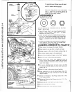
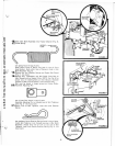
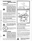
ASSEMBLY
1.1
nstall Lift Lev
er
using:
@0
two
Flat
Washers,
two
L
ockwashers
and
two
Hex
Nuts
found
in bag
of
parts.
a. Place Lift Lever (Fig. 1) over Lever
Quadrant
and
t
ilt
bottom
of
Lever
ou
tw
ard
to
align Bolts in Lift
Shaft
Wel
dme
nt
with
ho
les in Lever.
b.
In
stall Lift Lever
to
end
of
L
ift
Shaft
Weldment
(Fig. 1
).
Be s
ure
Lift Lev
er
Bracket
stradd
l
es
Lever
Quadrant
and
th
at
Lev
er
fits
on
end
of
Lift
Shaft.
Secure
with
F
lat
Wa
shers, Lockwashers
and
Hex Nuts.
Tighten
Nuts
se·
cu
rely.
c. Depress Lever Plunger
and
move Lift Lever
to
middle
of
Lever
Quadrant.
Drive Drive
Lock
P
in
th
rough
Lever,
Lever
Qua
d
rant
and
Lift Lever
Bracket.
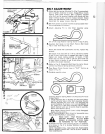
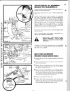
ASSEMBLE
MOWER
TO
TRACTO
r
1.
Check
tra
c
tor
tire pressure for
proper
inflation.
2.
Drive
tractor
to
an
area
that
is
smooth
and
leve
l.
3.
Position
mower
on
R.H. si
de
of
tractor
as
shown
(Fig.
2).
4.
Turn
tractor
steering
wheel
to
the
extreme
left.
5 .
Lock
all
four
A
tta
ch
ing Plungers in
the
"OUT"
position.
6.
Move
Lift
Lever
to
the
extreme
rear
position.
7. Slide mo
wer
under
tractor
until Suspension
Arms
are
direct
ly
bene
a
th
Hangar Brackets. NOTE: Be
sure
end
of
S
nu
bber
Pull
Rod
is
extending
to
front
of
tractor
and
be·
tween f
ro
nt
whee
ls.
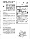
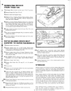
8 . F
or
ease in
attaching
mower
to
tracto
r, pl
ace
a
two
foot
long 2 x 4 (
or
similar
object
) f
lat
wise un
de
r
each
end
of
mower
(Fig. 3).
9.
Move Lift Lever
to
the
extreme
forward
position.
10.
Grasp suspension
arms
by
the
Spring
Boxe
s.
Raise R.H.
suspension
arms
and
a
li
gn wi
th
holes
in
Front
and
Rear
Hangar Brackets.
11.
Release
fro
nt Plunger
so
that
Plunger
enters
hole
in R.H.
Fr
o
nt
Hanger
Bracket
.
12.
Release rear Plunger
so
that
Plunger
en
t
ers
slot
in R. H. Rear
Ha
nger Br
ac
k
et
.
13
.Re
peat
st
eps
10
, 1 1
an
d
12
fo
r L.H. side
of
mower.
14
.Pu
ll
Li
ft
Lever
back
to lift
mower.
15
.
Remove
Blocks f
rom
un
der
each
end
of
mower.
-
FIGURE
3
2x4
...............................
. 2 .
another free manual from www.searstractormanuals.com